Poulan P14530ES User Manual - Page 6
Install Discharge Chute / Chute Rotator, Head See Fig. 7, Check Tire Pressure, Install Auger Control
 |
View all Poulan P14530ES manuals
Add to My Manuals
Save this manual to your list of manuals |
Page 6 highlights
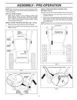
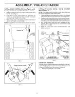
ASSEMBLY / PRE-OPERATION INSTALL AUGER CONTROL ROD (See Figs. 5 and 6) The auger control rod is installed on the snow thrower. 1. Remove plastic tie securing auger control rod to lower handle. (See Fig. 5). 2. Push down on the auger control rod and bring top end of rod up between the metal console and plastic console cover at right control lever. 3. With control lever in the raised position, insert end of control rod in slot of control lever. NOTE: Engage lever once and rod should snap into place. PLASTIC TIE AUGER CONTROL ROD INSTALL DISCHARGE CHUTE / CHUTE ROTATOR HEAD (See Fig. 7) NOTE: The multi-wrench provided in your parts bag may be used to install the chute rotator head. 1. Place discharge chute assembly on top of chute base with discharge opening toward front of snow thrower. 2. Position chute rotator head over chute bracket. If necessary, rotate chute assembly to align square and pin on underside of chute rotator head with holes in chute bracket. 3. With chute rotator head and chute bracket aligned, position chute rotator head on pin and threaded stud of mounting bracket. 4. Install 3/8 washer and locknut on threaded stud and tighten securely. CHUTE ROTATOR HEAD 3/8 LOCKNUT 3/8 WASHER FIG. 5 AUGER CONTROL LEVER AUGER CONTROL ROD FIG. 6 PIN THREADED STUD CHUTE ALIGN BEFORE BRACKET TIGHTENING LOCKNUT ROTATOR HEAD MOUNTING BRACKET FIG. 7 CHECK TIRE PRESSURE The tires on your snow thrower were overinflated at the factory for shipping purposes. Correct and equal tire pressure is important for best snow throwing performance. • Reduce tire pressure to 14-17 PSI. 6
-
 1
1 -
 2
2 -
 3
3 -
 4
4 -
 5
5 -
 6
6 -
 7
7 -
 8
8 -
 9
9 -
 10
10 -
 11
11 -
 12
12 -
13
-
14
-
15
-
16
-
17
-
18
-
19
-
20
-
21
-
22
-
23
-
24
-
25
-
26
-
27
-
28
-
29
-
30
-
31
-
32
-
33
-
34
-
35
-
36
-
37
-
38
-
39
-
40
 |
 |
