Poulan PB1842LT User Manual - Page 20
To Replace Mower Blade Drive Belt, See Fig. 18, To Level Mower Housing
 |
View all Poulan PB1842LT manuals
Add to My Manuals
Save this manual to your list of manuals |
Page 20 highlights
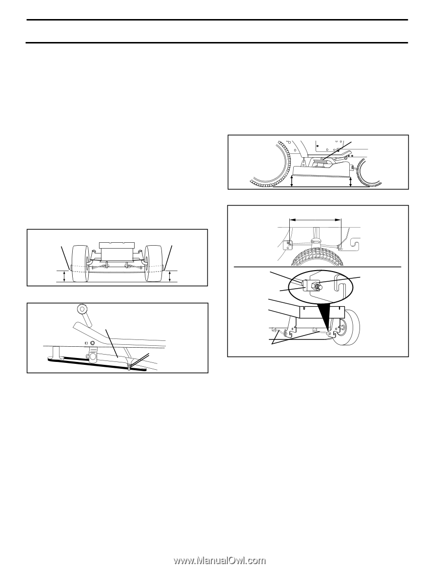
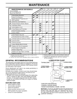
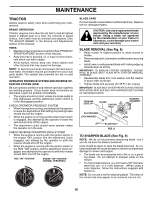
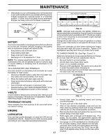
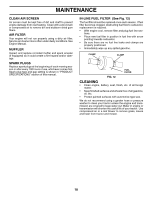
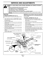
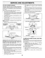
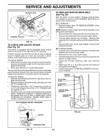
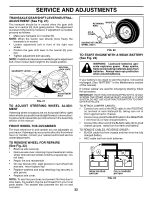
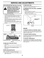
SERVICE AND ADJUSTMENTS TO LEVEL MOWER HOUSING Adjust the mower while tractor is parked on level ground or driveway. Make sure tires are properly inflated (See "PRODUCT SPECIFICATIONS" section of this manual). If tires are over or underinflated, you will not properly adjust your mower. SIDE-TO-SIDE ADJUSTMENT (See Figs. 14 and 15) • Raise mower to its highest position. • At the midpoint of both sides of mower, measure height from bottom edge of mower to ground. Distance "A" on both sides of mower should be the same or within 1/4" of each other. • If adjustment is necessary, make adjustment on one side of mower only. • To raise one side of mower, tighten lift link adjustment nut on that side. • To lower one side of mower, loosen lift link adjustment nut on that side. NOTE: Each full turn of adjustment nut will change mower height about 1/8". • Recheck measurements after adjusting. BOTTOM EDGE OF MOWER TO GROUND BOTTOM EDGE OF MOWER TO GROUND • When distance "D" is 1/8" to 1/2" lower at front than rear, tighten nuts "F" against trunnion on both front links. • To raise front of mower, loosen nut "F" from trunnion on both front links. Tighten nut "E" on both front links an equal number of turns. The two front links must remain equal in length. • When distance "D" is 1/8" to 1/2" lower at front than rear, tighten nut "F" against trunnion on both front links. • Recheck side-to-side adjustment. MANDREL "D" "D" FIG. 16 BOTH FRONT LINKS MUST BE EQUAL IN LENGTH A GROUND LINE A FIG. 14 NUT "F" TRUNNION NUT "E" SUSPENSION ARM LIFT LINK ADJUSTMENT NUT FRONT LINKS FIG. 17 FIG. 15 FRONT-TO-BACK ADJUSTMENT (See Figs. 16 and 17) IMPORTANT: DECK MUST BE LEVEL SIDE-TO-SIDE. IF THE FOLLOWING FRONT-TO-BACK ADJUSTMENT IS NECESSARY, BE SURE TO ADJUST BOTH FRONT LINKS EQUALLY SO MOWER WILL STAY LEVEL SIDE-TO-SIDE. To obtain the best cutting results, the mower housing should be adjusted so that the front is approximately 1/8" to 1/2" lower than the rear when the mower is in its highest position. Check adjustment on right side of tractor. Measure distance "D" directly in front and behind the mandrel at bottom edge of mower housing as shown. • Before making any necessary adjustments, check that both front links are equal in length. • If links are not equal in length, adjust one link to same length as other link. • To lower front of mower loosen nut "E" on both front links an equal number of turns. TO REPLACE MOWER BLADE DRIVE BELT (See Fig. 18) The mower blade drive belt may be replaced without tools. Park the tractor on level surface. Engage parking brake. BELT REMOVAL • Remove mower from tractor (See "TO REMOVE MOWER" in this section of this manual). • Work belt off both mandrel pulleys and idler pulleys. • Pull belt away from mower. BELT INSTALLATION • Install new belt in reverse order of removal. • Make sure belt is in all pulley grooves and inside all belt guides. • Install mower in reverse order of removal instruc- tions. 20
-
 1
1 -
2
-
3
-
4
-
5
-
6
-
7
-
8
-
9
-
10
-
11
-
12
-
13
-
14
-
 15
15 -
 16
16 -
 17
17 -
 18
18 -
 19
19 -
 20
20 -
 21
21 -
 22
22 -
 23
23 -
 24
24 -
 25
25 -
26
-
27
-
28
-
29
-
30
 |
 |