Poulan PB19546LT User Manual - Page 10
Reverse Operation System Ros See, Fig. 10, To Adjust Mower Cutting Height, See Fig. 8, To Adjust - lawn mower
 |
View all Poulan PB19546LT manuals
Add to My Manuals
Save this manual to your list of manuals |
Page 10 highlights
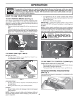
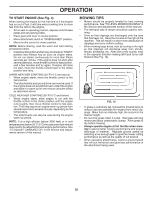
OPERATION • Start tractor with clutch/brake pedal depressed and gearshift lever in neutral position. • Move gearshift lever to desired position. • Slowly release clutch/brake pedal to start move- ment. IMPORTANT: Bring tractor to a complete stop before shifting or changing gears. Failure to do so will shorten the useful life of your transaxle. TO ADJUST MOWER CUTTING HEIGHT (See Fig. 8) The position of the attachment lift lever (A) determines the cutting height. A FIG. 8 • Put attachment lift lever in desired cutting height slot. The cutting height range is approximately 1" to 4". The heights are measured from the ground to the blade tip with the engine not running. These heights are approximate and may vary depending upon soil conditions, height of grass and types of grass being mowed. • The average lawn should be cut to approximately 2-1/2" during the cool season and to over 3" during hot months. For healthier and better looking lawns, mow often and after moderate growth. • For best cutting performance, grass over 6" in height should be mowed twice. Make the first cut relatively high; the second to desired height. TO ADJUST GAUGE WHEELS (See Fig. 9) Gauge wheels are properly adjusted when they are slightly off the ground when mower is at the desired cutting height in operating position. Gauge wheels then keep the deck in proper position to help prevent scalping in most terrain conditions. NOTE: Adjust gauge wheels with tractor on a flat level surface. • Adjust mower to desired cutting height (See "TO AD- JUST MOWER CUTTING HEIGHT" in this section of manual). • With mower in desired height of cut position, gauge wheels should be assembled so they are slightly off the ground. Install gauge wheel in appropriate hole. Tighten securely. • Repeat for all, installing gauge wheel in same adjustment hole. FIG. 9 REVERSE OPERATION SYSTEM (ROS) (See Fig. 10) Your tractor is equipped with a Reverse Operation System (ROS). Any attempt by the operator to travel in the reverse direction with the attachment clutch engaged will shut off the engine unless ignition key is placed in the ROS "ON" position. WARNING: Backing up with the attachment clutch engaged while mowing is strongly discouraged. Turning the ROS "ON", to allow reverse operation with the attachment clutch engaged, should only be done when the operator decides it is necessary to reposition the machine with the attachment engaged. Do not mow in reverse unless absolutely necessary. USING THE REVERSE OPERATION SYSTEM • Depress clutch/brake pedal all the way down and hold. • With engine running, turn ignition key counterclockwise to ROS "ON" position. • Look down and behind before backing. • Move gear shift lever to reverse (R) position and slowly release clutch/brake pedal to start movement. • When use of the ROS is no longer needed, turn the ignition key clockwise to engine "ON" position. ROS "ON" POSITION ENGINE "ON" POSITION (NORMAL OPERATING) FIG. 10 02828 10
-
 1
1 -
2
-
3
-
4
-
 5
5 -
 6
6 -
 7
7 -
 8
8 -
 9
9 -
 10
10 -
 11
11 -
 12
12 -
 13
13 -
 14
14 -
 15
15 -
16
-
17
-
18
-
19
-
20
-
21
-
22
-
23
-
24
-
25
-
26
-
27
-
28
-
29
-
30
-
31
-
32
-
33
-
34
-
35
-
36
-
37
-
38
-
39
-
40
-
41
-
42
-
43
-
44
-
45
-
46
-
47
-
48
-
49
-
50
-
51
-
52
 |
 |
