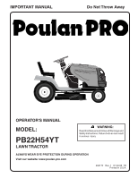
Poulan PB22H54YT User Manual - Page 5
Unassembled Parts, Assembly
 |
View all Poulan PB22H54YT manuals
Add to My Manuals
Save this manual to your list of manuals |
Page 5 highlights
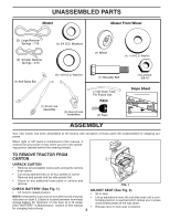
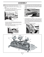
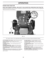
UNASSEMBLED PARTS Mower Mower Front Wheel (5) Large Retainer Springs - 7/16 (2) Smaller Retainer Springs - 5/16 (1) 3/4 O.D. Washers (1) Wheel (1) 1-1/4 O.D. Washer (1) Anti-Sway Bar (5) 1-3/16 O.D. Washers (1) Front Link Assembly (2) Rear Lift Link Assemblies (1) Shoulder Bolt (1) Oil Drain Tube For Future Use Keys (2) Keys (1) Locknut 3/8-16 Slope Sheet ASSEMBLY Your new tractor has been assembled at the factory with exception of those parts left unassembled for shipping purposes. When right or left hand is mentioned in this manual, it means from your point of view, when you are in the operating position (seated behind the steering wheel). TO REMOVE TRACTOR FROM CARTON L UNPACK CARTON • Remove all accessible loose parts and parts cartons from carton . • Cut along dashed lines on all four panels of carton. Remove end panels and lay side panels flat. • Check for any additional loose parts or cartons and remove. 02931 FIG. 1 CHECK BATTERY (See Fig. 1) • Lift hood to raised position. ADJUST SEAT (See Fig. 2) • Sit in seat. NOTE: If this battery is put into service after month and year • Lift up adjustment lever (A) and slide seat until a com- indicated on label (L) (label is located between terminals) fortable position is reached which allows you to press charge battery for minimum of one hour at 6-10 amps. clutch/brake pedal all the way down. (See "BATTERY" in Maintenance section of this manual for charging instructions). 5 • Release lever to lock seat in position.
-
 1
1 -
 2
2 -
 3
3 -
 4
4 -
 5
5 -
 6
6 -
 7
7 -
 8
8 -
 9
9 -
 10
10 -
 11
11 -
12
-
13
-
14
-
15
-
16
-
17
-
18
-
19
-
20
-
21
-
22
-
23
-
24
-
25
-
26
-
27
-
28
-
29
-
30
-
31
-
32
 |
 |
