Poulan PO15538LT User Manual - Page 6
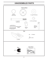
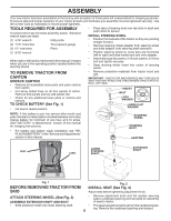
Assembly, Before Removing Tractor From, Tools Required For Assembly, Carton - maintenance parts
 |
View all Poulan PO15538LT manuals
Add to My Manuals
Save this manual to your list of manuals |
Page 6 highlights
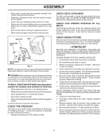
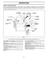
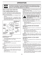
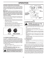
ASSEMBLY Your new tractor has been assembled at the factory with exception of those parts left unassembled for shipping purposes. To ensure safe and proper operation of your tractor all parts and hardware you assemble must be tightened securely. Use the correct tools as necessary to insure proper tightness. TOOLS REQUIRED FOR ASSEMBLY A socket wrench set will make assembly easier. Standard wrench sizes are listed. (1) 5/16" wrench Utility knife (2) 7/16" wrenches Tire pressure gauge (2) 1/2" wrenches Pliers (1) 9/16" wrench When right or left hand is mentioned in this manual, it means when you are in the operating position (seated behind the steering wheel). TO REMOVE TRACTOR FROM CARTON UNPACK CARTON • Remove all accessible loose parts and parts cartons from carton. • Cut along dotted lines on all four panels of carton. Remove end panels and lay side panels flat. • Check for any additional loose parts or cartons and remove. TO CHECK BATTERY (See Fig. 1) • Lift seat to raised position. • Place tabs of steering boot over tab slots in dash and push down to secure. INSTALL STEERING WHEEL • Position front wheels of the tractor so they are pointing straight forward. • Remove steering wheel adapter from steering wheel and slide adapter onto steering shaft extension. • Position steering wheel so cross bars are horizontal (left to right) and slide inside boot and onto adapter. • Assemble large flat washer, 5/16 lock washer, 5/16 hex bolt and tighten securely. • Snap steering wheel insert into center of steering wheel. • Remove protective materials from tractor hood and grill. IMPORTANT: CHECK FOR AND REMOVE ANY STAPLES IN SKID THAT MAY PUNCTURE TIRES WHERE TRACTOR IS TO ROLL OFF SKID. INSERT BOLT LOCK WASHER LARGE FLAT WASHER NOTE: If this battery is put into service after month and year indicated on label (label is located between terminals) charge battery for minimum of one hour at 6-10 amps. (See "BATTERY" in Maintenance section of this manual for charging instructions). • For battery and battery cable installation see "REPLACING BATTERY" in the "Service and Adjustments" section in this manual. STEERING WHEEL STEERING BOOT ADAPTER SEAT LABEL LOWER STEERING SHAFT EXTENSION SHAFT 02819 02602 Fig. 1 BEFORE REMOVING TRACTOR FROM SKID Fig. 2 INSTALL SEAT (See Fig. 3) Adjust seat before tightening adjustment knob. ATTACH STEERING WHEEL (See Fig. 2) ASSEMBLE EXTENSION SHAFT AND BOOT • Slide extension shaft onto lower steering shaft. • • 6 Remove adjustment knob and flat washer securing seat to cardboard packing and set aside for assembly of seat to tractor. Pivot seat upward and remove from the cardboard packing. Remove the cardboard packing and discard.
-
 1
1 -
 2
2 -
 3
3 -
 4
4 -
 5
5 -
 6
6 -
 7
7 -
 8
8 -
 9
9 -
 10
10 -
 11
11 -
 12
12 -
13
-
14
-
15
-
16
-
17
-
18
-
19
-
20
-
21
-
22
-
23
-
24
-
25
-
26
-
27
-
28
 |
 |
