Poulan PO5524 Assembly Instructions - Page 6
Handle Assembly, RH Includes Foam Grip - parts
 |
View all Poulan PO5524 manuals
Add to My Manuals
Save this manual to your list of manuals |
Page 6 highlights
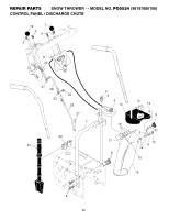
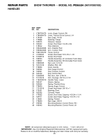
REPAIR PARTS HANDLES SNOW THROWER - - MODEL NO. PO5524 (96197000100) KEY PART NO. NO. DESCRIPTION 1 178875X479 Lever, Auger Control, RH 2 178648X479 Lever, Traction Drive Control, LH 3 179439 Nut, Cage 1/4-20 4 178888 Bushing, Flange 5 169675 Retainer, Hairpin 6 180402 Screw, Hex Head 1/4-20 x 3/4 7 178652 Rod, Interlock 8 196333X008 Arm, Impeller Rod 9 196334X008 Arm, Traction Rod 10 196619X479 Panel, Control 11 74780524 Screw, Hex Head 5/16-18 x 1-1/2 12 74780512 Screw, Hex Head 13 199693 Handle Assembly, LH (Includes Foam Grip) 14 199692 Handle Assembly, RH (Includes Foam Grip) 15 73800500 Nut, Lock 5/16-18 16 19131316 Washer, Flat 3/8 17 178899 Knob, Handle 18 184594 Rod, Auger Control 19 193081 Rod, Traction Control 20 180428 End, Control Rod 21 73350500 Nut, Hex, Jam 5/16-18 22 72120618 Bolt, Carriage 3/8-16 x 2-1/4 23 178643X479 Handle Tube, Lower 24 180447 Sleeve, Spring 25 180926 Spring, Traction Drive 26 178669 Spring, Auger Control 27 71210616 Screw, Hex Head 3/8-16 x 1 28 175331 Bushing, Pivot 30 183352 Console, Panel 31 175262 Screw, Hex Head, Tapping #10-24 x 1-1/4 32 184471 Screw, Hex Head, Tapping #10-24 x 1/2 36 178831 Spring, Torsion 41 178890 Nut, Cage 3/8-16 47 196944 Mounting Bracket, Control Panel, RH 48 196943 Mounting Bracket, Control Panel, LH NOTE: All component dimensions given in U.S. inches. 1 inch = 25.4 mm IMPORTANT: Use only Original Equipment Manufacturer (O.E.M.) replacement parts. Failure to do so could be hazardous, damage your lawn mower and void your warranty. 25
-
 1
1 -
 2
2 -
 3
3 -
 4
4 -
 5
5 -
 6
6 -
 7
7 -
 8
8 -
 9
9 -
 10
10 -
 11
11 -
 12
12
 |
 |
