Poulan PP291E30 User Manual - Page 11
To Move Forward And Backward See Fig. 16, Using The Clean-out Tool See Fig. 15
 |
View all Poulan PP291E30 manuals
Add to My Manuals
Save this manual to your list of manuals |
Page 11 highlights
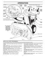
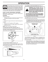
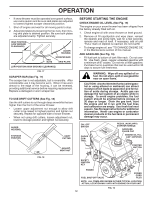
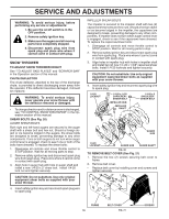
OPERATION TO THROW SNOW (See Fig. 14) The auger rotation is controlled by the auger control lever located on the right side handle. • Squeeze auger control lever to handle to engage the auger and throw snow. • Release the auger control lever to stop throwing snow. AUGER CONTROL LEVER FIG. 14 USING THE CLEAN-OUT TOOL (See Fig. 15) In certain snow conditions, the discharge chute may become clogged with ice and snow. Use the clean-out tool to dislodge this blockage. When cleaning, repairing, or inspecting, make certain all controls are disengaged and the auger/impeller and all moving parts have stopped. Disconnect the spark plug wire and keep the wire away from the spark plug to prevent accidental starting. • Release the auger control lever and shut off the engine. • Remove the clean-out tool from it's mounting clip. Grasp the tool firmly by the handle and push and twist the tool into the discharge chute to dislodge the blockage. After the packed snow has been dislodged, return the cleanout tool to it's mounting clip by pushing it into the clip. • Make sure the discharge chute is pointed in a safe direction (no vehicles, buildings, people, or other objects are in the direction of discharge) before restarting the engine. • Restart the engine, then squeeze the auger control lever to the handle to clear snow from the auger housing and the discharge chute. DISCHARGE CHUTE TO MOVE FORWARD AND BACKWARD (See Fig. 16) SELF-PROPELLING, forward and reverse movement of the snow thrower, is controlled by the traction drive control lever located on the left side handle. • Squeeze traction drive control lever to handle to engage the drive system. • Release traction drive control lever to stop the forward or reverse movement of the snow thrower. SPEED and DIRECTION are controlled by the drive speed control lever. • Press downward on the speed control lever and move lever to desired position BEFORE engaging the traction drive control lever. Be sure lever springs back and locks into desired position. CAUTION: Do not move speed control lever when traction drive control lever is engaged. Damage to the snow thrower can result. • Slower speeds are for heavier snow and faster speeds are for light snow and transporting the snow thrower. It is recommended that you use a slower speed until you are familiar with the operation of the snow thrower. NOTE: When both traction drive and auger control levers are engaged, the traction drive control lever will lock the auger control lever in the engaged position. This will allow you to release your right hand from the handle and adjust the discharge chute direction without interrupting the snow throwing process. TRACTION DRIVE CONTROL LEVER DRIVE SPEED CONTROL LEVER FIG. 16 CLEAN-OUT TOOL MOUNTING CLIP FIG. 15 TO ADJUST SKID PLATES (See Fig. 17) NOTE: The wrench provided in your parts bag may be used to adjust the skid plates. Skid plates are located on each side of the auger housing and adjust the clearance between the scraper bar and the ground surface. Adjust skid plates evenly to proper height for current surface conditions. For removal of snow in normal conditions, such as a paved driveway or sidewalk, place skid plates in the highest position (lowest scraper clearance) to give a 1/8" clearance between the scraper bar and the ground. Use a middle position if the surface to be cleared is uneven. NOTE: It is not recommended to operate the snow thrower over gravel or rocky surfaces. Objects such as gravel, rocks or other debris, can easily be picked up and thrown by the impeller, which can cause serious personal injury, property damage or damage to the snow thrower. 11
-
 1
1 -
2
-
3
-
4
-
5
-
 6
6 -
 7
7 -
 8
8 -
 9
9 -
 10
10 -
 11
11 -
 12
12 -
 13
13 -
 14
14 -
 15
15 -
 16
16 -
17
-
18
-
19
-
20
-
21
-
22
-
23
-
24
-
25
-
26
-
27
-
28
-
29
-
30
-
31
-
32
-
33
-
34
-
35
-
36
-
37
-
38
-
39
-
40
 |
 |
