Poulan PP800EPS24 User Manual
Poulan PP800EPS24 Manual
 |
View all Poulan PP800EPS24 manuals
Add to My Manuals
Save this manual to your list of manuals |
Poulan PP800EPS24 manual content summary:
- Poulan PP800EPS24 | User Manual - Page 1
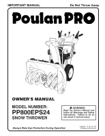
IMPORTANT MANUAL Do Not Throw Away OWNER'S MANUAL MODEL NUMBER: PP800EPS24 SNOW THROWER WARNING: Read the Owner's Manual and follow all Warnings and Safety Instructions. Failure to do so can result in serious injury. Always Wear Eye Protection During Operation 440645 11.09.10 TH Printed in the - Poulan PP800EPS24 | User Manual - Page 2
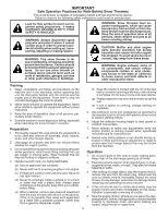
WARNING: Snow throwers have exposed rotating parts, which can follow all instructions on the machine and in the manual(s) before snow thrower. 4. If the unit should start to vibrate abnormally, stop the engine (motor) and check immediately for the cause. Vibration is generally a warning of trouble - Poulan PP800EPS24 | User Manual - Page 3
technicians and the proper tools to service or repair this unit. Please read and retain this manual. The instructions will enable you to assemble and maintain your snow thrower properly. Always observe the "SAFETY RULES". SERIAL NUMBER DATE OF PURCHASE THE MODEL AND SERIAL NUMBERS WILL BE FOUND - Poulan PP800EPS24 | User Manual - Page 4
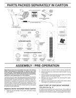
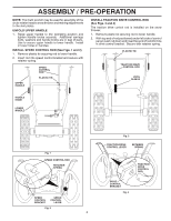
these instructions and this manual in its entirety before you attempt to assemble or operate your new snow thrower. Reading the entire manual will necessary to ensure proper tightness. REMOVE SNOW THROWER FROM CARTON 1. Remove all accessible loose parts and parts boxes from carton. 2. Cut down - Poulan PP800EPS24 | User Manual - Page 5
thrower and making adjustments to the skid plates. UNFOLD UPPER HANDLE 1. Raise upper handle to the operating position and tighten handle knobs securely. Additional carriage bolts, washers and handle knobs are in bag of parts rod is installed on the snow thrower. 1. Remove plastic tie securing - Poulan PP800EPS24 | User Manual - Page 6
5 and 6) 1. Retrieve vinyl sleeve and spring from bag of parts and retrieve the auger control rod from carton chute tray. Slide straight parts bag may be used to install the chute rotator head. 1. Place discharge chute assembly on top of chute base with discharge opening toward front of snow thrower - Poulan PP800EPS24 | User Manual - Page 7
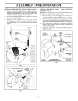
5/16-18 CARRIAGE BOLT CABLE EYELET REMOTE CABLE BRACKET 5/16-18 LOCKNUT Fig. 8 CHUTE DEFLECTOR CONTROL LEVER Fig. 9 CHECK TIRE PRESSURE The tires on your snow thrower were overinflated at the factory for shipping purposes. Correct and equal tire pressure is important for best - Poulan PP800EPS24 | User Manual - Page 8
adjustments. Save this manual for future reference. These symbols may appear on your snow thrower or in literature supplied with the product. Learn and understand their meaning. DANGER OR WARNING PRIMER FORWARD REVERSE READ AND FOLLOW ALL SAFETY INFORMATION AND INSTRUCTIONS BEFORE USE OF THIS - Poulan PP800EPS24 | User Manual - Page 9
CHUTE LH TURN TRIGGER LIGHT CLEAN-OUT TOOL HANDLE KNOB MUFFLER TOOLBOX AUGERS SKID PLATE Fig. 10 MEETS A.N.S.I. SAFETY REQUIREMENTS Our snow throwers conform to the standards of the American National Standards Institute. Toolbox - used to store spare shear bolts, locknuts and wrench. Safety - Poulan PP800EPS24 | User Manual - Page 10
a warm engine. • To engage choke, turn knob counterclockwise. Slowly turn knob clockwise to disengage. TO CONTROL SNOW DISCHARGE (See Fig. 12) WARNING: Snow throwers have exposed rotating parts, which can cause severe injury from contact, or from material thrown from the discharge chute. Keep the - Poulan PP800EPS24 | User Manual - Page 11
snow. Use the clean-out tool to dislodge this blockage. When cleaning, repairing, or inspecting, make certain all controls are disengaged and the auger/impeller and all moving parts SELF-PROPELLING, forward and reverse movement of the snow thrower, is controlled by the traction drive control lever - Poulan PP800EPS24 | User Manual - Page 12
parts service before requiring replacement. Replace a damaged or worn scraper bar. BEFORE STARTING THE ENGINE CHECK ENGINE OIL LEVEL (See Fig. 18) The engine on your snow thrower Maintenance section of this manual. ADD GASOLINE (See Fig. avoid engine problems, the fuel Storage Instructions for - Poulan PP800EPS24 | User Manual - Page 13
Volt A.C. three-wire grounded system. Serious personal injury or damage to your snow thrower could result. COLD START - ELECTRIC STARTER 1. Insert safety ignition key ( snow conditions. See "TO ADJUST SKID PLATES" in this section of this manual. • For extremely heavy snow, reduce the width of snow - Poulan PP800EPS24 | User Manual - Page 14
thrower as instructed in this manual. Some adjustments will need to be made periodically to properly maintain your snow thrower. At least once a season, check to see if you should make any of the adjustments described in the Service and Adjustments section of this manual. • At least once a year, you - Poulan PP800EPS24 | User Manual - Page 15
adjustable. Replace belts if they begin to slip from wear. (See "TO REMOVE BELT COVER" in the Service and Adjustments section of this manual). The belts on your snow thrower are of special construction and should be replaced by original equipment manufacturer (OEM) belts available from your nearest - Poulan PP800EPS24 | User Manual - Page 16
any service or adjustments: 1. Be sure the on/off switch is in the OFF position. 2. Remove safety ignition key. 3. Make sure the augers and all moving parts have completely stopped. 4. Disconnect spark plug wire from spark plug and place wire where it cannot come in contact with plug. SNOW THROWER - Poulan PP800EPS24 | User Manual - Page 17
snow thrower are of special construction and should be replaced by original equipment manufacturer (OEM) belts available from your nearest service center chute to be removed from snow thrower. 3. REMOVE BELT COVER - See "TO REMOVE BELT COVER" in this section of this manual. 4. REMOVE ENGINE PULLEY - Poulan PP800EPS24 | User Manual - Page 18
ENGINE See engine manual. CARBURETOR Your carburetor is not adjustable. Engine performance should not be affected at altitudes up to 7,000 feet (2,134 meters). If your engine does not operate properly due to suspected carburetor problems, take your snow thrower to a qualified service center. ENGINE - Poulan PP800EPS24 | User Manual - Page 19
, etc. Store in a clean, dry area. 1. Clean entire snow thrower (See "CLEANING" in the Maintenance section of this manual). 2. Inspect and replace belts, if necessary (See "TO REPLACE BELTS" in the Service and Adjustments section of this manual). 3. Lubricate as shown in the Maintenance section of - Poulan PP800EPS24 | User Manual - Page 20
TROUBLESHOOTING See appropriate section in manual unless directed to an authorized service center/department. PROBLEM position. 6. Prime as instructed in the Operation section of this manual. 7. Wait a few authorized service center/department. Loss of snow discharge or slowing of snow discharge - Poulan PP800EPS24 | User Manual - Page 21
REPAIR PARTS SNOW THROWER - MODEL NUMBER PP800EPS24 (96198003901) AUGER HOUSING / IMPELLER ASSEMBLY 1 KEY NO. 1 2 3 4 PART NO. 404928X428 404931X431 72270505 155377 DESCRIPTION AUGER HOUSING SCRAPPER BAR CARRIAGE BOLT 5/16−18 X .625 NUT 5/16−18 3 (5x) 4 (5x) 2 01.07.001-A 2 1 KEY NO. 1 2 PART - Poulan PP800EPS24 | User Manual - Page 22
REPAIR PARTS SNOW THROWER - MODEL NUMBER PP800EPS24 (96198003901) AUGER HOUSING / IMPELLER ASSEMBLY 5 15 14 4 11 6 11 16 .4 mm IMPORTANT: Use only Original Equipment Manufacturer (O.E.M.) replacement parts. Failure to do so could be hazardous, damage your snow thrower and void your warranty. 22 - Poulan PP800EPS24 | User Manual - Page 23
REPAIR PARTS SNOW THROWER - MODEL NUMBER PP800EPS24 (96198003901) AUGER HOUSING / IMPELLER ASSEMBLY KEY NO. 1 2 3 4 5 6 7 8 9 10 11 12 13 14 15 16 17 18 19 20 21 22 23 24 25 26 27 28 29 30 31 32 33 34 35 36 37 PART NO. 175321X431 427148 188909 427146 175322 178675X431 192199 405400 73800400 - Poulan PP800EPS24 | User Manual - Page 24
REPAIR PARTS SNOW THROWER - MODEL NUMBER PP800EPS24 (96198003901) AUGER HOUSING / IMPELLER ASSEMBLY 2 3 1 1 2 3 01.07.024-B KEY NO. 1 2 3 PART NO. 420478 411939 179582 DESCRIPTION AUGER BEARING BEARING PLUG SCREW 5/16−18 X 1.00 4 4 01.11.001-B 3 2 3 KEY PART NO. NO. DESCRIPTION 1 - Poulan PP800EPS24 | User Manual - Page 25
PARTS SNOW THROWER - MODEL NUMBER PP800EPS24 (96198003901) CONTROL PANEL / CHUTE 5 7 15 3 16 *14 KEY NO. 1 2 3 4 5 6 7 8 9 *10 *11 *12 *13 *14 15 16 PART ITEMS SHIPPED LOOSE WITH PRODUCT. 2. ITEMS 15 AND 16 ARE SERVICE PART NUMBERS TO ALLOW PURCHASE OF INDIVIDUAL ITEMS IF NECESSARY. NOTE: All - Poulan PP800EPS24 | User Manual - Page 26
PARTS SNOW THROWER - MODEL NUMBER PP800EPS24 (96198003901) CONTROL PANEL / CHUTE 2 2 *3 1 *7 *6 KEY NO. 1 2 *3 *4 *5 *6 *7 PART NOTES: 1. ITEMS INDICATED WITH AN * ARE LISTED AS REFERENCE FOR SERVICE PARTS ONLY. 2 1 KEY NO. 1 2 PART NO. 421249 74041024 DESCRIPTION STEER CABLE SCREW 10 - Poulan PP800EPS24 | User Manual - Page 27
REPAIR PARTS SNOW THROWER - MODEL NUMBER PP800EPS24 (96198003901) HANDLES 5 1 6 8 5 8 6 2 39 7 8 49 7 KEY PART 5/16−18 9 155415 WASHER 01.08.003-A 1 KEY PART NO. NO. DESCRIPTION 1 419797X431 LOWER HANDLE 2 427513X431 PIVOT SUPPORT WELDMENT 3 428867 SCREW 5/16−18 X .750 2 4 - Poulan PP800EPS24 | User Manual - Page 28
REPAIR PARTS SNOW THROWER - MODEL NUMBER PP800EPS24 (96198003901) HANDLES 10 2 11 9 5 7 6 8 47 9 1 3 13 8 13 14 12 12 14 01.08.002-G KEY NO. 1 2 3 4 5 6 7 8 9 10 11 12 13 14 PART NO. 412683X431 424517X431 424516X431 412679X008 426918X008 412677 421613 169675 17060410 414280 414281 178899 - Poulan PP800EPS24 | User Manual - Page 29
REPAIR PARTS SNOW THROWER - MODEL NUMBER PP800EPS24 (96198003901) HANDLES 10 1 2 10 3 8 9 4 KEY NO. 1 2 3 4 5 6 7 8 9 10 PART NO. 180480 405740 180445 187716 180447 178669 180926 72270505 155377 169675 DESCRIPTION IMPELLER ROD TRACTION ROD SHIFTER ROD TOP SHIFTER ROD BOTTOM SPRING SLEEVE - Poulan PP800EPS24 | User Manual - Page 30
REPAIR PARTS SNOW THROWER - MODEL NUMBER PP800EPS24 (96198003901) HANDLES 7 3 2 4 5 5 6 41 01.10.007-B KEY PART NO. NO. 1 182906 2 178668 3 180927 4 184471 5 175262 6 178770 7 183784 DESCRIPTION CONSOLE PANEL HEADLIGHT BEZEL FLOOD HEADLIGHT SHOULDER SCREW 10−24 X .625 SCREW 10−24 - Poulan PP800EPS24 | User Manual - Page 31
REPAIR PARTS SNOW THROWER - MODEL NUMBER PP800EPS24 (96198003901) DRIVE 6 7 1b 8 4 3 1b 7 1a 5 6 2 3 4 01.03.002-A KEY NO. 1 1a 1b 2 3 4 5 6 7 8 PART NO. 404923 404307 184206 402691 174697 179830 146315 17490508 155443 189282 DESCRIPTION AXLE ASSEMBLY (assy of 1a,1b) AXLE SHAFT ROLL PIN - Poulan PP800EPS24 | User Manual - Page 32
REPAIR PARTS SNOW THROWER - MODEL NUMBER PP800EPS24 (96198003901) DRIVE 42 EXPLODED 2 16 1 17 15 14 15 12 9 11 11 = 25.4 mm IMPORTANT: Use only Original Equipment Manufacturer (O.E.M.) replacement parts. Failure to do so could be hazardous, damage your snow thrower and void your warranty. 32 - Poulan PP800EPS24 | User Manual - Page 33
REPAIR PARTS SNOW THROWER - MODEL NUMBER PP800EPS24 (96198003901) DRIVE KEY NO. 1 2 3 4 5 6 7 8 9 10 11 12 13 14 15 16 17 18 19 20 21 22 23 24 25 26 27 PART NO. DESCRIPTION 198875 17501010 402685X428 17490508 57079 405485 198580 403097X008 402881 403096X431 191730 402856X008 416717X431 187101 - Poulan PP800EPS24 | User Manual - Page 34
REPAIR PARTS SNOW THROWER - MODEL NUMBER PP800EPS24 (96198003901) CHASSIS / ENGINE / PULLEYS 2 3 2 3 1 1 01.00.034-A KEY NO. - 1 2 3 PART NO. - - - - - 418694X428 150406 428867 DESCRIPTION B&S ENGINE 12A114-1354-E8 FRAME BOLT 3/8-16 SCREW 5/16-18 X .750 KEY NO. 1 PART NO. 436146X428 - Poulan PP800EPS24 | User Manual - Page 35
REPAIR PARTS SNOW THROWER - MODEL NUMBER PP800EPS24 (96198003901) CHASSIS / ENGINE / PULLEYS 23 22 14 24 21 20 11 14 21 13 20 12 14 15 6 7 10 8 01.21.003-C 19 18 17 16 5 4 3 9 2 KEY PART NO. NO. DESCRIPTION 1 2 3 4 5 6 7 8 9 10 11 12 13 14 15 1 16 17 18 19 20 21 22 23 24 408007 - Poulan PP800EPS24 | User Manual - Page 36
REPAIR PARTS SNOW THROWER - MODEL NUMBER PP800EPS24 (96198003901) WHEELS 1 2 01.06.017-A KEY NO. 1 2 PART NO. 432333X421 432334X421 DESCRIPTION WHEEL ASSEMBLY LH WHEEL ASSEMBLY RH 1 2 01.15.003-C 4 3 KEY NO. 1 2 3 4 PART NO. 410293 410294 17490408 17600406 DESCRIPTION CABLE BRACKET LH - Poulan PP800EPS24 | User Manual - Page 37
REPAIR PARTS SNOW THROWER - MODEL NUMBER PP800EPS24 (96198003901) WHEELS 2 2 17 23 43 1 20 19 16 17 18 15 22 16 24 65 7 98 10 20 23 21 11 22 19 21 12 14 1011 9 1214 13 13 8 2 7 6 5 34 1 2 01.15.001-B KEY NO. 1 PART NO. 405161 DESCRIPTION COVER 2 184471 SHOULDER - Poulan PP800EPS24 | User Manual - Page 38
REPAIR PARTS SNOW THROWER - MODEL NUMBER PP800EPS24 (96198003901) BAG OF PARTS 3 2 01.14.003-B 4 6 5 7 8 9 10 1 12 11 KEY NO. 1 2 3 4 5 6 7 8 9 10 11 12 PART NO. 198563 169675 180684X008 184505 179829 191730 72250505 751153 73800600 19131316 192090 73800400 DESCRIPTION POWER CORD - Poulan PP800EPS24 | User Manual - Page 39
REPAIR PARTS SNOW THROWER - MODEL NUMBER PP800EPS24 (96198003901) DECALS 1 4 9 6 1 3 11 KEY NO. 1 3 4 6 9 11 - - - PART NO. 181037 181035 181042 181033 429591 429590 440645 440646 DESCRIPTION DECAL, DANGER DECAL, DANGER, DEFLECTOR DECAL, DANGER DECAL, INSTRUCTION DECAL, SPEED CONTROL - Poulan PP800EPS24 | User Manual - Page 40
without charge for parts or labor incurred in replacing parts, any part which we in accordance with the instructions furnished. This Warranty does Poulan Pro Outdoor Products Customer Service Dept. 9335 Harris Corners Parkway Charlotte, NC 28269 USA In Canada contact: Poulan Pro, Customer Service
-
 1
1 -
 2
2 -
 3
3 -
 4
4 -
 5
5 -
 6
6 -
 7
7 -
8
-
9
-
10
-
11
-
12
-
13
-
14
-
15
-
16
-
17
-
18
-
19
-
20
-
21
-
22
-
23
-
24
-
25
-
26
-
27
-
28
-
29
-
30
-
31
-
32
-
33
-
34
-
35
-
36
-
37
-
38
-
39
-
40
 |
 |
OWNER'S MANUAL
MODEL NUMBER:
PP800EPS24
SNOW THROWER
Always Wear Eye Protection During Operation
IMPORTANT MANUAL
Do Not Throw Away
WARNING:
Read the Owner's Manual and
follow all Warnings and Safety
Instructions.
Failure to do so
can result in serious injury.
440645
11.09.10
TH
Printed in the U.S.A.