Poulan PP8527ESA User Manual - Page 11
To Move Forward And Backward See Fig. 15
 |
View all Poulan PP8527ESA manuals
Add to My Manuals
Save this manual to your list of manuals |
Page 11 highlights
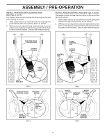
OPERATION HIGH POSITION KNOB CAUTION: Do not move speed control lever when traction drive control lever is engaged. Damage to the snow thrower can result. • Slower speeds are for heavier snow and faster speeds are for light snow and transporting the snow thrower. It is recommended that you use a slower speed until you are familiar with the operation of the snow thrower. NOTE: When both traction drive and auger control levers are engaged, the traction drive control lever will lock the auger control lever in the engaged position. This will allow you to release your right hand from the handle and adjust the discharge chute direction without interrupting the snow throwing process. CHUTE DEFLECTOR LOW POSITION FIG. 13 TO THROW SNOW (See Fig. 14) The auger rotation is controlled by the auger control lever located on the right side handle. • Squeeze auger control lever to handle to engage the auger and throw snow. • Release the auger control lever to stop throwing snow. AUGER CONTROL LEVER TRACTION DRIVE CONTROL LEVER DRIVE SPEED CONTROL LEVER FIG. 15 POWER STEERING OPERATION (See Fig. 16) Steering triggers are used to assist in steering your snow thrower. The triggers are located on the underside of each handle.When a trigger is squeezed, it disengages the drive wheel on that side of snow thrower and allows it to turn in that direction. • To turn left - squeeze left side trigger. • To turn right - squeeze right side trigger. FIG. 14 TO MOVE FORWARD AND BACKWARD (See Fig. 15) SELF-PROPELLING, forward and reverse movement of the snow thrower, is controlled by the traction drive control lever located on the left side handle. • Squeeze traction drive control lever to handle to engage the drive system. • Release traction drive control lever to stop the forward or reverse movement of the snow thrower. SPEED and DIRECTION are controlled by the drive speed control lever. • Press downward on the speed control lever and move lever to desired position BEFORE engaging the trac- tion drive control lever. Be sure lever springs back and locks into desired position. 11 LH TURN RH TURN TRIGGER TRIGGER FIG. 16
-
 1
1 -
2
-
3
-
4
-
5
-
 6
6 -
 7
7 -
 8
8 -
 9
9 -
 10
10 -
 11
11 -
 12
12 -
 13
13 -
 14
14 -
 15
15 -
 16
16 -
17
-
18
-
19
-
20
 |
 |
