Poulan PRFT22H50A User Manual - Page 8
To Attach Nose Roller See Fig. 5, Install Mower, And Drive Belt, See Figs. 6 And 7
 |
View all Poulan PRFT22H50A manuals
Add to My Manuals
Save this manual to your list of manuals |
Page 8 highlights
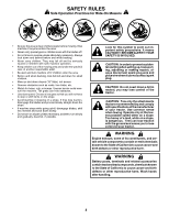
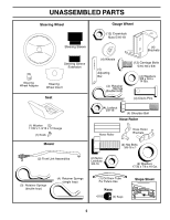
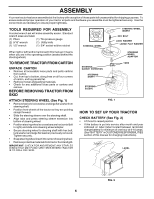
ASSEMBLY TO ATTACH NOSE ROLLER (See Fig. 5) • Position brackets, 17/32 x 7/8 x 16 gauge washers, and nose roller between deck mounting brackets as shown. Be sure to position brackets on correct side, as shown. • Install 3/8-16 x 1 hex bolts and 3/8-16 lock nuts as shown. Tighten hardware securely. NOTE: Be sure bracket tabs are positioned in tab holes in deck brackets. • Slide mower under tractor with discharge guard to right side of tractor. IMPORTANT: CHECK BELT FOR PROPER ROUTING IN ALL MOWER PULLEY GROOVES. INSTALL BELT INTO ELECTRIC CLUTCH PULLEY GROOVE. • Install one front link in top hole of the L.H. front mower bracket and L.H. front suspension bracket. Retain with two single loop retainer springs as shown. HEX BOLT TAB HOLE NOSE ROLLER "B" BRACKET TAB • Install second front link in R.H. front suspension bracket only and retain with single loop retainer spring as shown. • Slide right side of mower back and install link in top hole of R.H. front mower bracket. Retain with single loop retainer spring as shown. • Turn height adjustment knob counterclockwise until it stops. "A" BRACKET TAB FIG. 5 LOCK NUT WASHER • Lower mower linkage with attachment lift control. • Place the suspension arms on inward pointing deck pins. If necessary, rock and raise front of mower to align deck pins with the holes in suspension arms. Retain with double loop retainer springs with loops down as shown. INSTALL MOWER AND DRIVE BELT (See Figs. 6 and 7) • Connect anti-sway bar to chassis bracket under left footrest and retain with double loop retainer spring. • Turn height adjustment knob clockwise to remove slack Be sure tractor is on level surface and mower suspension from mower suspension. arms are raised with attachment lift control. Engage parking brake. • Cut and remove ties securing anti-sway bar and belts. Swing anti-sway bar to left side of mower deck. • Raise deck to highest position. • Adjust gauge wheels before operating mower as shown in the Operation section of this manual. FRONT DOUBLE LOOP RETAINER SUSPENSION ARMS SUSPENSION BRACKETS CHASSIS BRACKET SPRING (Inward pointing deck pins) FRONT MOWER ELECTRIC BRACKET CLUTCH FRONT PULLEY LINKS GAUGE WHEEL SINGLE LOOP RETAINER SPRINGS DOUBLE LOOP RETAINER SPRING ANTI-SWAY BAR USE PLIERS FOR RETAINER SPRINGS IDLER PULLEY LOOP DOWN FIG. 6 8 DISCHARGE GUARD
-
 1
1 -
2
-
 3
3 -
 4
4 -
 5
5 -
 6
6 -
 7
7 -
 8
8 -
 9
9 -
 10
10 -
 11
11 -
 12
12 -
 13
13 -
14
-
15
-
16
-
17
-
18
-
19
-
20
-
21
-
22
-
23
-
24
-
25
-
26
-
27
-
28
-
29
-
30
-
31
-
32
-
33
-
34
-
35
-
36
-
37
-
38
-
39
-
40
-
41
-
42
-
43
-
44
-
45
-
46
-
47
-
48
-
49
-
50
-
51
-
52
 |
 |
