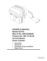
Poulan QCT42 User Manual - Page 5
Assembly - bagger
 |
View all Poulan QCT42 manuals
Add to My Manuals
Save this manual to your list of manuals |
Page 5 highlights
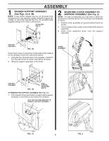
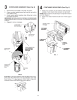
ASSEMBLY 1 BAGGER SUPPORT ASSEMBLY (See Figs. 1A & 1B) NOTE: If your tractor already has four (4) shoulder bolts installed on the rear drawbar, simply hang the support assembly on the bolts. Discard the four (4) shoulder bolts supplied and go on to Step 2 instructions. SHOULDER BOLTS 2 MOUNTING COVER ASSEMBLY TO SUPPORT ASSEMBLY (See Fig. 2) NOTE: For ease of assembly, you may wish to obtain the assistance of another person for mounting cover assembly to tractor. 1. Position cover assembly on ground behind tractor as shown. 2. Lift and rotate cover to align cover bracket with support assembly. 3. Slide cover assembly down onto the support assembly. 02645 SUPPORT ASSEMBLY FIG. 1A If your tractor does not have four (4) shoulder bolts installed on the drawbar, follow the instructions below. 1. Using the four formed holes in the drawbar, install the four shoulder bolts as shown and tighten securely. 2. Hang the support assembly on the bolts. COVER ASSEMBLY SUPPORT ASSEMBLY 02644 SUPPORT ASSEMBLY FIG. 1B SELF TAPPING SHOULDER BOLTS TO REMOVE THE SUPPORT ASSEMBLY (See Fig. 1C) 1. Pull outward on the stop bracket enough to allow support assembly to be lifted up and away from drawbar. PULL OUT ON STOP BRACKET TO REMOVE SUPPORT ASSEMBLY 02643 FIG. 1C 5 FIG. 2 02646
-
 1
1 -
 2
2 -
 3
3 -
 4
4 -
 5
5 -
 6
6 -
 7
7 -
 8
8 -
 9
9 -
 10
10 -
 11
11 -
12
-
13
 |
 |
