Poulan SM400 User Manual - Page 5
Assembly - spark plug
 |
View all Poulan SM400 manuals
Add to My Manuals
Save this manual to your list of manuals |
Page 5 highlights
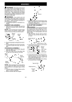
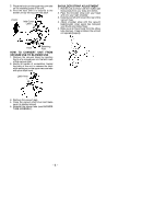
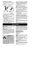
ASSEMBLY WARNING: Stop engine and be sure the impeller blades have stopped turning before opening the vacuum inlet door or attempting to insert or remove the vacuum or blower tubes. The rotating blades can cause serious injury. Always disconnect the spark plug before performing maintenance or accessing movable parts. WARNING: If you receive your unit assembled, check each step to insure your unit is properly assembled and all fasteners are secure. Follow all safety information in the manual and on the unit. D A standard screwdriver is required for as- sembly. BLOWER TUBE ASSEMBLY 1. Align the rib on the blower tube with the groove in the blower outlet; slide the tube into place. NOTE: Knob must be loose enough to allow blower tube to be inserted in blower outlet. Loosen knob by turning counterclockwise. Blower Outlet Blower Tube Groove Rib 2. Secure the tube by turning the knob clockwise. 3. To remove the tube, turn the knob counterclockwise to loosen the tube; remove the tube. VACUUM BAG ASSEMBLY 1. Open the zipper on the vacuum bag and insert the elbow tube. 2. Push the small end of the elbow tube through the small opening in the bag. Elbow Tube Small Opening Zipper Opening Rib NOTE: Make sure edge of the small opening is flush against the flared area of the elbow tube, and the rib on the elbow tube is on the bottom. 3. Close the zipper on the bag. Make sure the zipper is closed completely. 4. Remove blower tube from engine. Rib Groove 5. Insert the elbow tube into the blower outlet. Make sure elbow tube rib is aligned with the blower outlet groove. 6. Turn knob clockwise to secure elbow tube. VACUUM TUBE ASSEMBLY WARNING: Stop engine and be sure the impeller blades have stopped turning before opening the vacuum inlet door or attempting to insert or remove the vacuum or blower tubes. The rotating blades can cause serious injury. 1. Align the lower vacuum tube as shown. Push lower vacuum tube into upper vacuum tube. Upper Vacuum Tube Lower Vacuum Tube 2. Insert the tip of a screwdriver into the latch area of the vacuum inlet. Latch Area Blower Outlet Latch Area Vacuum Inlet Cover 3. Gently tilt the handle of the screwdriver toward the back of the unit to release the latch while pulling up on the vacuum inlet cover with your other hand. 4. Hold the vacuum inlet cover open until up- per vacuum tube is installed. Vacuum Inlet Retaining Post Vacuum Inlet Cover -- 5 --
-
 1
1 -
 2
2 -
 3
3 -
 4
4 -
 5
5 -
 6
6 -
 7
7 -
 8
8 -
 9
9 -
 10
10 -
 11
11 -
12
-
13
 |
 |
