ProForm 1200 Zlt Treadmill Uk Manual - Page 9
Press the Left Handrail Cover 100 against
 |
View all ProForm 1200 Zlt Treadmill manuals
Add to My Manuals
Save this manual to your list of manuals |
Page 9 highlights
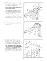
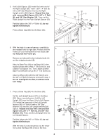
8. Set the console assembly face down on a soft surface to avoid scratching the console assembly. Identify the Right Handrail (105), which is marked with a "Right" sticker. Hold the Right Handrail near the console assembly. Next, insert the console wire through the indicated holes in the Right Handrail (105) as shown. 8 Console Assembly Console Wire Holes 105 9. Attach the Left Handrail (101) and the Right Handrail (105) to the console assembly with four #8 x 1/2" Screws (2), two 3/8" x 3/4" Patch Bolts (8), and two 3/8" Star Washers (10). Do not tighten the Screws or Patch Bolts yet. 9 8 101 10 105 2 8 10 2 Console Assembly 10. Press the Left Handrail Cover (100) against the console assembly. See the inset drawing. Align the lip on the Left Handrail Cover with the lip on the console assembly. Then, fully tighten the four #8 x 1/2" Screws (2) in the Left Handrail (101). Note: The Screws are preattached. Repeat this step with the Right Handrail Cover (107). Tighten two 1/4" x 1/2" Patch Bolts (3) into the Handrails (101, 105) and the console assembly. See step 9. Fully tighten the four #8 x 1/2" Screws (2) and the two 3/8" x 3/4" Patch Bolts (8). 10 100 22 3 2 107 101 Lips 9 23 105 Console Assembly
-
 1
1 -
2
-
3
-
 4
4 -
 5
5 -
 6
6 -
 7
7 -
 8
8 -
 9
9 -
 10
10 -
 11
11 -
 12
12 -
 13
13 -
 14
14 -
15
-
16
-
17
-
18
-
19
-
20
-
21
-
22
-
23
-
24
-
25
-
26
-
27
-
28
-
29
-
30
-
31
-
32
-
33
-
34
-
35
-
36
 |
 |
