ProForm 135 Csx Bike English Manual - Page 20
How To Adjust The Drive Belt
 |
View all ProForm 135 Csx Bike manuals
Add to My Manuals
Save this manual to your list of manuals |
Page 20 highlights
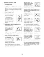
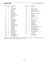
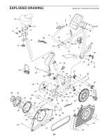
HOW TO ADJUST THE DRIVE BELT If the pedals slip while you are pedaling, even while the resistance is adjusted to the highest level, the drive belt may need to be adjusted. To adjust the drive belt, you must remove the parts described below. Loosen the Post Knob (18) a few turns, pull it outward, and remove the Seat Post (10). Then, using an adjustable wrench, remove the Post Knob. See the EXPLODED DRAWING on page 23. Identify the Left and Right Shields (21, 22). Remove all of the screws from the Left and Right Shields; there are two sizes of screws in the shields-note which size of screw you remove from each hole. Then, gently remove the Right Shield. Next, loosen the Adjustment Screw (47). Then, tighten the Idler Screw (45) until the Drive Belt (59) is tight. 59 18 10 16 22 29 47 45 When the Drive Belt (59) is tight, tighten the Adjustment Screw (47). 23 Then, reattach the left and right shields, the right lock ring, the right pedal, the post cover, the post knob, and the seat post. Using a standard screwdriver, release the tabs along the bottom edge of the Post Cover (16) and remove it. Then, using an adjustable wrench, turn the Right Pedal (29) counterclockwise and remove it. Using a standard screwdriver, release the tabs around the edge of the right Lock Ring (23), and then remove it from the Right Shield (22). 20
-
 1
1 -
2
-
3
-
4
-
5
-
6
-
7
-
8
-
9
-
10
-
11
-
12
-
13
-
14
-
 15
15 -
 16
16 -
 17
17 -
 18
18 -
 19
19 -
 20
20 -
 21
21 -
 22
22 -
 23
23 -
 24
24
 |
 |
