ProForm 280 Treadmill English Manual - Page 7
Lift the treadmill frame see HOW TO FOLD
 |
View all ProForm 280 Treadmill manuals
Add to My Manuals
Save this manual to your list of manuals |
Page 7 highlights
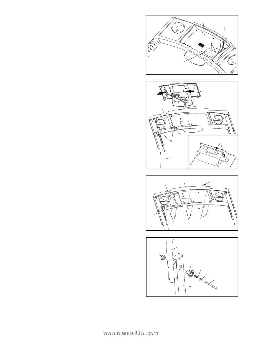
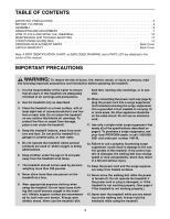
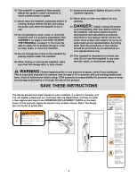
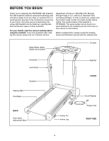
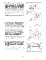
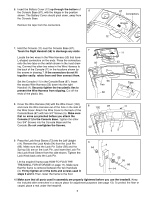
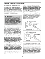
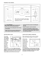
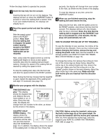
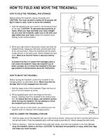
6. Insert the Battery Cover (12) up through the bottom of 6 the Console Base (87), with the hinges in the position shown. The Battery Cover should pivot down, away from the Console Base. Remove the tape from the connectors. 87 Connectors Hinges 12 7. Hold the Console (11) near the Console Base (87). Touch the Right Handrail (59) to discharge any static. Locate the two wires in the Wire Harness (53) that have L-shaped connectors on the ends. Press the connectors onto the two tabs on the switch shown in the inset drawing. Connect the other two wires in the Wire Harness to the back of the Console (11) in the locations shown by the arrows in drawing 7. If the connectors do not fit together easily, rotate them and then connect them. Set the Console (11) in the Console Base (87). Insert the excess Wire Harness (53) down into the right Handrail (4). Securely tighten the two plastic ties to prevent the Wire Harness from slipping. Cut off the ends of the plastic ties. 7 87 53 Ties 59 11 53 Tabs 8. Cover the Wire Harness (53) with the Wire Cover (102), and route the Wire Harness out of the hole in the side of the Wire Cover. Attach the Wire Cover to the back of the Console Base (87) with two 3/4" Screws (5). Make sure that no wires are pinched before you attach the Console (11) to the Console Base. Tighten the other four 3/4" Screws into the Console Base and the Console. Do not overtighten the Screws. 8 102 87 11 53 5 55 9. Press the Lock Knob Sleeve (73) into the Left Upright (14). Remove the Lock Knob (54) from the Lock Pin (66). Make sure that the Lock Pin Collar (56) and the Spring (55) are on the Lock Pin, and insert the Lock Pin into Lock Knob Sleeve from the side shown. Tighten the Lock Knob back onto the Lock Pin. Lift the treadmill frame (see HOW TO FOLD THE TREADMILL FOR STORAGE on page 11). Make sure that the frame is centered between the two Handrails (4). Firmly tighten all of the bolts and screws used in steps 3 and 4. Then, lower the frame to the floor. 9 54 4 73 55 56 66 14 10.Make sure that all parts used in assembly are properly tightened before you use the treadmill. Keep the included allen wrenches in a secure place for adjustment purposes (see page 13). To protect the floor or carpet, place a mat under the treadmill. 7
-
 1
1 -
 2
2 -
 3
3 -
 4
4 -
 5
5 -
 6
6 -
 7
7 -
 8
8 -
 9
9 -
 10
10 -
 11
11 -
 12
12 -
13
-
14
-
15
-
16
-
17
-
18
-
19
 |
 |