ProForm 380 Cs Treadmill English Manual - Page 11
Attach the Latch Housing 48 to the Left - belt
 |
View all ProForm 380 Cs Treadmill manuals
Add to My Manuals
Save this manual to your list of manuals |
Page 11 highlights
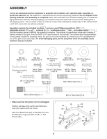
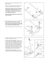
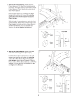
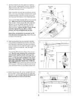
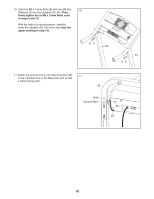
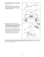
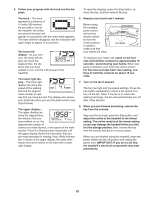
12. See the lower drawing. Position the Uprights (53, 54) so that the Frame (51) is centered be- 12 tween them. See the upper drawing. Firmly tighten the two M10 x 60mm Bolts (1) and the four M10 x 75mm Bolts (2). Be careful not to overtighten the M10 x 60mm Bolts. 1 2 51 Top View 54 51 53 13. Attach the Latch Housing (48) to the Left Upright (53) with two #10 x 1" Tek Screws (109); start both Screws, and then tighten each of them. Make sure that the large hole in the Latch Housing is on the indicated side. Locate the Latch Pin Assembly (24). Remove the knob from the pin. Make sure that the collar and the spring are on the pin. (Note: If there are two collars, place one on each side of the spring.) Insert the pin into the Latch Housing (48). Then, tighten the knob onto the pin. 13 24 48 Knob 109 Large Hole 53 Spring Collar Pin 14. Make sure that all parts are properly tightened before you use the treadmill. Keep the included hex keys in a secure place. One hex key is used to adjust the walking belt (see page 20). To protect the floor or carpet, place a mat under the treadmill. 11
-
 1
1 -
2
-
3
-
4
-
5
-
 6
6 -
 7
7 -
 8
8 -
 9
9 -
 10
10 -
 11
11 -
 12
12 -
 13
13 -
 14
14 -
 15
15 -
 16
16 -
17
-
18
-
19
-
20
-
21
-
22
-
23
-
24
-
25
-
26
-
27
-
28
 |
 |
