ProForm 50 Gts Treadmill English Manual - Page 5
Assembly
 |
View all ProForm 50 Gts Treadmill manuals
Add to My Manuals
Save this manual to your list of manuals |
Page 5 highlights
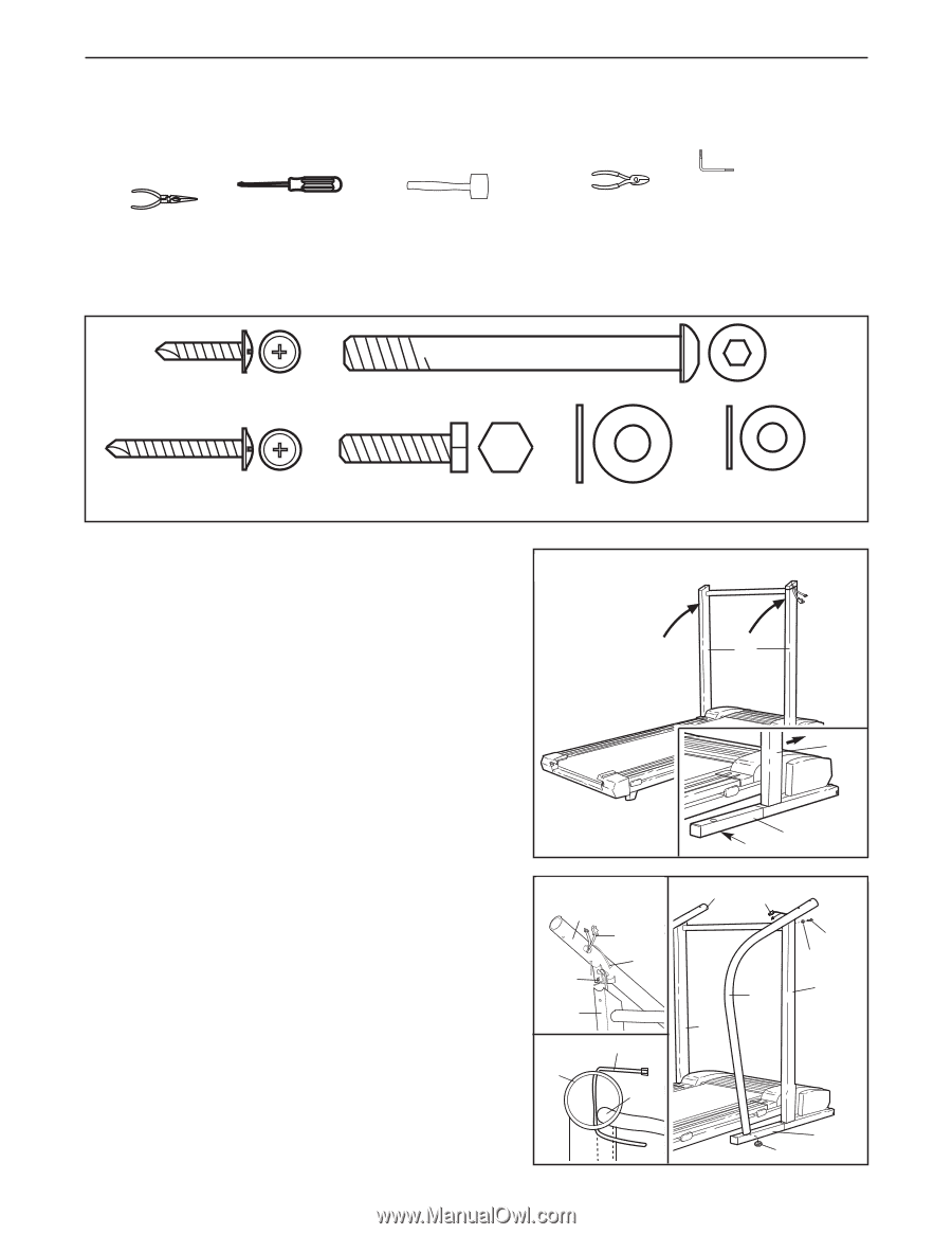
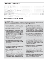
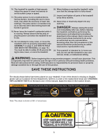
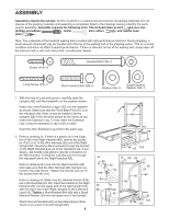
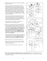
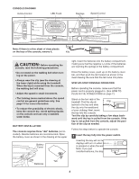
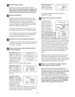
ASSEMBLY Assembly requires two people. Set the treadmill in a cleared area and remove all packing materials. Do not dispose of the packing materials until assembly is completed. Refer to the drawings below to identify the parts used in assembly. Assembly requires the following tools: The included allen wrench and your own phillips screwdriver , mallet wire cutters and needle-nose pliers . Note: The underside of the treadmill walking belt is coated with high-performance lubricant. During shipping, a small amount of lubricant may be transferred to the top of the walking belt or the shipping carton. This is a normal condition and does not affect treadmill performance. If there is lubricant on top of the walking belt, simply wipe off the lubricant with a soft cloth and a mild, non-abrasive cleaner. Screw (101)-4 Handrail Bolt (78)-2 Whe Long Screw (79)-4 Short Handrail Bolt (89)-2 Washer (36)-2 Small Handrail Washer (29)-2 H 1. With the help of a second person, carefully raise the Uprights (82) until the treadmill is in the position shown. Insert one of the Extension Legs (103) into the treadmill as shown. Make sure that the Thick Base Pad (97) is on the indicated side. Note: It may be helpful to tip the Uprights (82) in the direction shown by the arrow as you insert the Extension Leg. To fully insert the Extension Leg, it may be necessary to tap it with a mallet. Insert the other Extension Leg (103) in the same way. 2. Refer to drawing 2a. If there is a plastic tie in the Cage Nut (109) in the Right Handrail (85), remove the plastic tie. Pull 5 to 6" of the Wire Harness (26) out of the Right Upright (82). Route the Wire Harness through the bracket on the Right Handrail and out of the indicated hole. If necessary, use needle-nose pliers to grip the connectors on the Wire Harness. Thread the included wire tie through the indicated hole in the Right Handrail (85). Refer to drawing 2b. Look into the Right Handrail (85) and make sure that the Wire Harness (26) has been secured to the side shown. Tighten the wire tie and cut off the excess from the end. Refer to drawing 2c. Make sure the Handrail Inserts (102) are in the Handrails (23, 85). Insert the bracket on the Right Handrail (85) into the upper end of the right Upright (82), with the lower end of the Right Handrail on the Extension Leg (103). Tighten a Short Handrail Bolt (89) with a Small Handrail Washer (29) into the upper end of the Upright. Attach the Left Handrail (23) as described above. Note: There is not a wire in the left Upright (82). 5 1 82 82 97 103 2a 85 109 26 Tie 82 2b Tie 85 26 2c 23 26 85 82 89 29 82 103 102
-
 1
1 -
 2
2 -
 3
3 -
 4
4 -
 5
5 -
 6
6 -
 7
7 -
 8
8 -
 9
9 -
 10
10 -
 11
11 -
12
-
13
-
14
-
15
-
16
-
17
-
18
 |
 |