ProForm 500 F Elliptical English Manual - Page 9
Nylon Locknut; the Seat Bracket
 |
View all ProForm 500 F Elliptical manuals
Add to My Manuals
Save this manual to your list of manuals |
Page 9 highlights
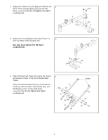
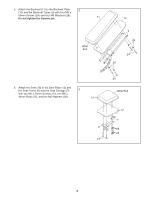
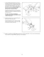
7. Insert the Backrest Bracket (8) into the slot in 7 the Frame (1) as shown. Next, grease an M10 x 180mm Bolt (23). Then, attach the Seat Frame (6) and the Backrest Tubes (9) to the Frame (1) with the Bolt, two M10 Washers (30), and an M10 Nylon Locknut (2). Do not overtighten the Nylon Locknut; the Seat Bracket and Backrest Tubes must pivot easily. Engage the Adjustment Knob into the Backrest Bracket. Then, tighten the Adjustment Knob (15) into the Frame (1). See step 4 and tighten the M8 Nylon Locknuts (29). See step 5 and tighten the M6 x 60mm Screws (24). 8. Attach the Seat Pin (14) to the Seat Frame (6) 8 with an M4 x 15mm Screw (20). Insert the Seat Pin (14) into a hole in the Seat Frame (6) and the Frame (1). Note: For clarity, the seat is not shown in this step. 2 30 15 9 8 30 23 Slot 6 1 Grease 1 20 6 14 9. Make sure all parts are properly tightened before you use the weight bench. The use of the remaining parts will be explained in ADJUSTMENT, beginning on the next page. 9
-
 1
1 -
2
-
3
-
 4
4 -
 5
5 -
 6
6 -
 7
7 -
 8
8 -
 9
9 -
 10
10 -
 11
11 -
 12
12 -
 13
13 -
 14
14 -
15
-
16
 |
 |
