ProForm 520 Zni Treadmill English Manual - Page 6
Assembly
 |
View all ProForm 520 Zni Treadmill manuals
Add to My Manuals
Save this manual to your list of manuals |
Page 6 highlights
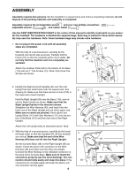
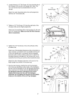
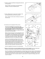
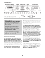
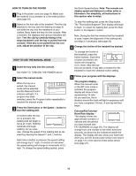
ASSEMBLY Assembly requires two persons. Set the treadmill in a cleared area and remove all packing materials; do not dispose of the packing materials until assembly is completed. Assembly requires the included allen wrench and your own phillips screwdriver , adjustable wrench , and rubber mallet . Use the PART IDENTIFICATION CHART in the center of this manual to identify small parts as you assemble the treadmill. The hardware is divided into separate bags. Each bag is marked to show which assembly step uses the hardware. Note: Some hardware bags may include extra hardware. 1. Do not plug in the power cord until all assembly 1 steps are completed. 51 With the help of a second person, carefully tip the treadmill onto its left side as shown. Partially fold the Frame (51) so that the treadmill will be more stable. Do not fully fold the treadmill until it is completely assembled. 13 44 116 44 Attach the six Base Pads (44) to the bottom of the Base (116) with six 1" Tek Screws (13). Note: Only three Tek 13 Screws are shown. 2. Identify the Right and Left Uprights (55, 64); the Left Upright has two small holes near the square post. See drawing 2a. Make sure that there are two U-nuts (100) in the lower end of each Upright. Hold the Right Upright (55) near the Base (116), and orient the Right Upright as shown. Make sure that the Right Upright bends in the direction shown. Straighten the Wire Harness (49), and feed it into the lower end of the Right Upright and out of the upper end. Make sure no wires are pinched. Hand tighten two Upright Bolts (112) with Star Washers (111) into the bottom of the Base (116) and the lower end of the Right Upright. Attach the Left Upright (64) as described above. Note: 3. With the help of a second person, carefully tip the treadmill back down so that the Uprights (55, 64 [not shown]) are vertical. Make sure that the end of the Wire Harness (49) does not fall into the Right Upright. Set the Console Base (38) on the Right Upright (55) as shown. Check the pins in the connector on the Wire Harness (49) and make sure that they are straight. Connect the Wire Harness to the indicated connector on the back of the Console Base. Make sure to insert the connectors properly (see the inset drawing). The connectors should slide easily and snap into place. If the connectors do not slide easily and snap into place, turn one connector and try again. 6 2 112 111 49 3 38 55 116 Holes 55 Bend 64 2a 55, 64 100 49 49
-
 1
1 -
 2
2 -
 3
3 -
 4
4 -
 5
5 -
 6
6 -
 7
7 -
 8
8 -
 9
9 -
 10
10 -
 11
11 -
 12
12 -
13
-
14
-
15
-
16
-
17
-
18
-
19
-
20
-
21
-
22
-
23
-
24
-
25
-
26
-
27
-
28
-
29
-
30
-
31
 |
 |
