ProForm 525e Treadmill English Manual - Page 6
Place the Console Base 46 on the Uprights 11. Pull out
 |
View all ProForm 525e Treadmill manuals
Add to My Manuals
Save this manual to your list of manuals |
Page 6 highlights
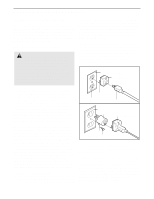
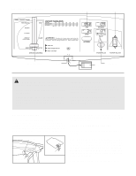
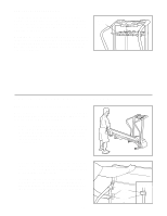
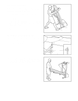
3. Attach the Weight Rack (90) to the Uprights (11) with the two Washers (39) and Rack Bolts (89). Note: If necessary, spread the Uprights apart to align the holes in the Weight Rack with the holes in the Upright. Insert the Left and Right Handrails (1, 88) into the upper end of the Uprights (11), with the lower end of each Handrail on the outside of the Extension Leg (34) as shown. Have a second person hold the Handrails until step 4 is completed. 4. With the help of a second person, lower the Uprights (11) until the Left and Right Handrails (1, 88) are resting on the floor. Attach the lower end of the Right Handrail to the Extension Leg (34) with a Handrail Bolt (91), Handrail Washer (92), and Handrail Nut (93) as shown. Note: It may be necessary to push on the lower end of the Handrail to align the hole in the Handrail with the hole in the Extension Leg. Attach the Left Handrail to the left Extension Leg (not shown) as described above. Raise the Uprights (11) to the position shown in step 3. 5. Cut and remove the plastic tie holding the Wires (21). Place the Console Base (46) on the Uprights (11). Pull out just enough of the two Wires (21) to connect them to the connectors in the Console Base. Make a loop with the indicated plastic tie and insert the end through the tie holder on the bottom of the Console Base. Plug the Wire with the red connector into the corresponding connector in the Console Base. If the connectors do not fit together without being forced, rotate the red connector and try again. Do not force the connectors together. Next, plug the other Wire into the other connector in the Console Base. Important: Make sure that both Wires are fully inserted. WARNING: Do not disconnect or connect the Wires while the treadmill power cord is plugged in. Tighten the plastic tie and cut off the end. Loosely thread four Screws (33) into the Uprights (11) and the Console Base (46). After all four Screws have been started, tighten the Screws until they are snug; do not overtighten the Screws. 6. Attach the Storage Latch (14) to the left Upright (11) with two Small Screws (13). Be careful not to overtighten the Screws. Place the Weights on the Weight Rack (90) with the 3 lbs. Weights (79) in the center of the Rack and 2 lbs. Weights next, followed by the 1 lbs. Weights. 3 39 89 90 39 89 11 11 1 88 4 11 88 5 11 Plastic Tie 34 34 93 92 91 Plastic Tie 21 Connectors 46 33 6 90 11 13 14 79 7. Make sure that all parts are tightened before you use the treadmill. Keep the included allen wrench in a secure place. The allen wrench is used to adjust the walking belt (see page 13). To protect the floor or carpet, place a mat under the treadmill. 6
-
 1
1 -
 2
2 -
 3
3 -
 4
4 -
 5
5 -
 6
6 -
 7
7 -
 8
8 -
 9
9 -
 10
10 -
 11
11 -
 12
12 -
13
-
14
-
15
-
16
-
17
-
18
-
19
 |
 |
