ProForm 545e English Manual - Page 7
Arm Bushings 42 in the Pedal Arm. Note: These
 |
View all ProForm 545e manuals
Add to My Manuals
Save this manual to your list of manuals |
Page 7 highlights
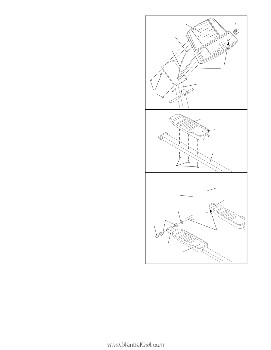
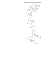
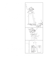
3. While another person holds the Console (6) near the Upright (3), connect the console wire to the Extension 3 6 Wire (63). Console Make sure the slack Resistance Cable (26) is pulled Wire up out of the Upright (3). Feed the slack Extension Wire (63) down into the Upright (3). Push the excess 63 Resistance Cable into the Console (6). Attach the Console to the Upright with four M4 x 16mm Round Head Screws (38). Be careful to avoid pinching the Resistance Cable and the Extension Wire. Press the Resistance Knob (50) onto the Resistance Cable (26). 3 38 50 26 3. Find the Left Pedal (31), which has a ridge on the 3 right side. Attach the Left Pedal to one of the Pedal Arms (12) with three M4 x 19mm Round Head Screws (16) as shown. Repeat this step to attach the Right Pedal to the other Pedal Arm (not shown). 4. Locate the Left Handlebar (8) (there is an "L" sticker on the Left Handlebar for identification). Apply a thin film of the included grease to the axle at the lower end of the Left Handlebar. Slide a Handlebar Spacer (39) and the Pedal Arm (12) with the Left Pedal (31) onto the Left Handlebar (8) as shown. Make sure that there are two Pedal Arm Bushings (42) in the Pedal Arm. (Note: These parts fit tightly; it may be helpful to use the rubber mallet). Next, refer to the PART IDENTIFICATION CHART on page 5 and identify the 3/4" Axle Caps (43). Tap a 3/4" Axle Cap onto the Left Handlebar. Repeat this step to attach the other Pedal Arm (12) to the Right Handlebar (62). 16 4 8 39 42 43 12 31 Ridge 31 12 62 12 Grease 7
-
 1
1 -
 2
2 -
 3
3 -
 4
4 -
 5
5 -
 6
6 -
 7
7 -
 8
8 -
 9
9 -
 10
10 -
 11
11 -
 12
12 -
13
-
14
-
15
-
16
 |
 |