ProForm 590qs English Manual - Page 6
Assembly - parts
 |
View all ProForm 590qs manuals
Add to My Manuals
Save this manual to your list of manuals |
Page 6 highlights
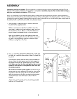
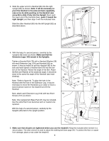
ASSEMBLY Assembly requires two people. Set the treadmill in a cleared area and remove all packing materials. Do not dispose of the packing materials until assembly is completed. Assembly requires the included allen wrench and your own phillips screwdriver . Note: The underside of the treadmill walking belt is coated with high-performance lubricant. During shipping, a small amount of lubricant may be transferred to the top of the walking belt or the shipping carton. This is a normal condition and does not affect treadmill performance. If there is lubricant on top of the walking belt, simply wipe off the lubricant with a soft cloth and a mild, non-abrasive cleaner. 1. With the help of a second person, carefully raise the treadmill to the upright position. While a second person tips the treadmill to one side and holds it, insert one of the Extension Legs (103) into the treadmill as shown. Make sure that the Extension Leg is turned so the Base Pad (97) is on the bottom. Next, tip the treadmill to the other side and insert the other Extension Leg (not shown) in the same way. Lower the side of the treadmill so that both Extension Legs (103) are resting flat on the floor. 1 103 97 2. Refer to HOW TO LOWER THE TREADMILL FOR USE on page 18. Follow the instructions in step 2 to lower the treadmill. Hold the latch spacer and the latch support together as shown. Attach the latch spacer and the latch support to the center hole in the left Upright (82) with a 3/4Ó Screw (89). Make sure that the Screw is tight, but do not overtighten it; if the Screw is overtightened, the latch will not slide smoothly. Be careful to hold the parts together. Inset drawing A shows how the Latch Assembly fits together. Inset drawing B shows how the springs fit into the bracket. Make sure that the tabs on the latch are touching the bracket and that the back end of the latch is flush with the bracket. Attach the Latch Assembly (77) to the left Upright (82) with two 3/4Ó Screws (89). 2 Latch Spacer 82 77 89 89 Latch Support A Bracket Latch B Spring Flush Spring Tabs 6
-
 1
1 -
 2
2 -
 3
3 -
 4
4 -
 5
5 -
 6
6 -
 7
7 -
 8
8 -
 9
9 -
 10
10 -
 11
11 -
 12
12 -
13
-
14
-
15
-
16
-
17
-
18
-
19
-
20
-
21
-
22
-
23
-
24
-
25
-
26
 |
 |
