ProForm 6.5q Uk Manual - Page 6
Small Screws.
 |
View all ProForm 6.5q manuals
Add to My Manuals
Save this manual to your list of manuals |
Page 6 highlights
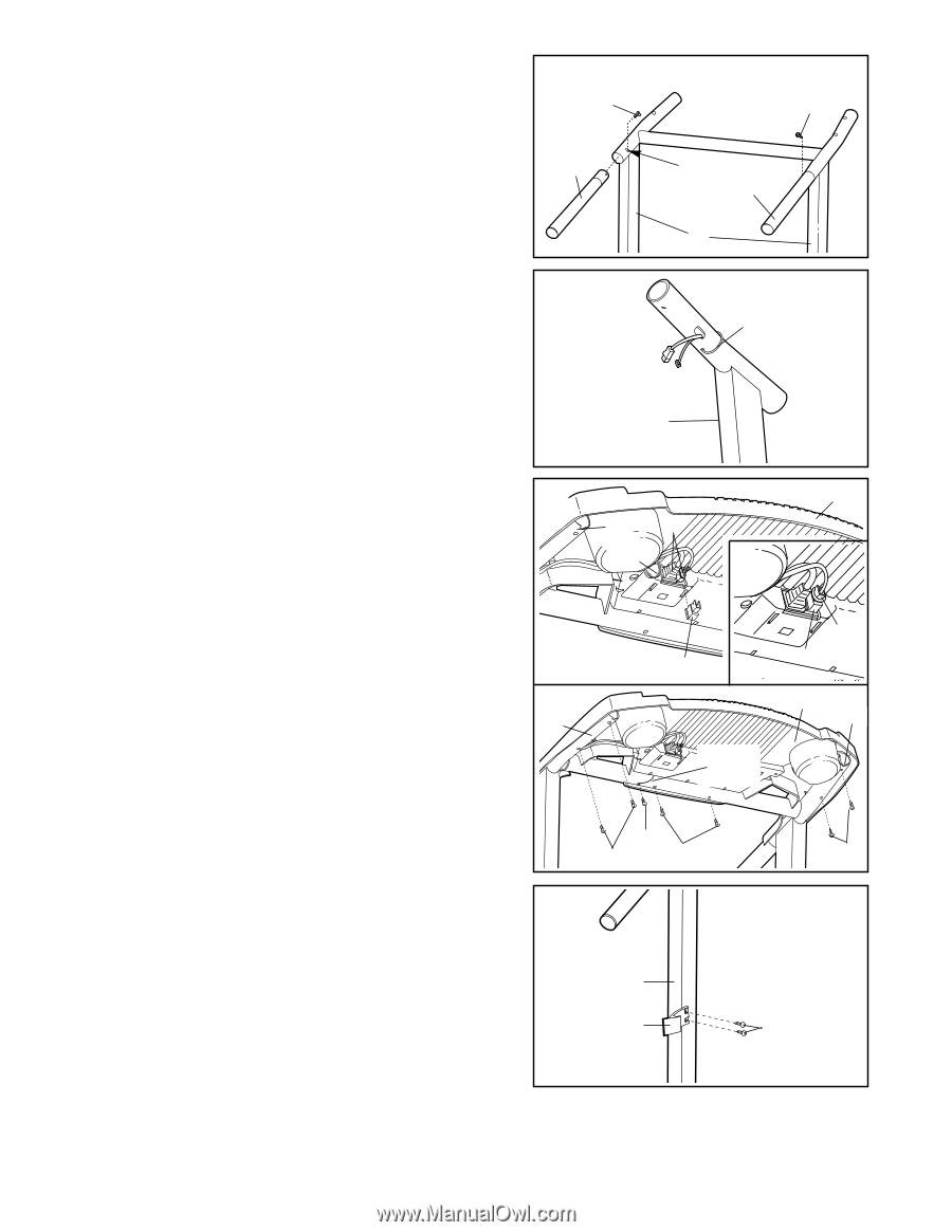
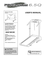
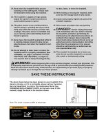
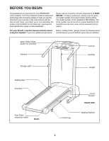
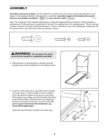
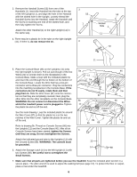
3. Remove the Handrail Screw (53) from one of the Handrails (1). Insert the Handrail into the tube at the top of the left Upright (11), and align the hole in the Handrail with the slotted hole in the Upright. Loosely thread the Handrail Screw into the Handrail, rotate the Handrail until the Screw is touching one end of the slotted hole, and then fully tighten the Screw. Attach the other Handrail (1) to the right Upright (11) in the same way. 4. There may be a plastic tie in the tube on the right Upright (11). If there is, do not remove the tie. 3 53 1 4 53 Slotted Hole 1 11 Tie 11 5. Place the Console Base (46) on the Uprights (11) (only the right Upright is shown). Pull out just enough of the two 5a 46 Wires (21) to connect them to the receptacles in the Console Base. Make a loop with the indicated plastic tie and insert the end through the tie holder on the bottom of 11 21 Tie the Console Base. Locate the Wire that has a two-pin connector and a three-pin connector. Plug the connectors into the matching receptacles in the Console Base. If the connectors do not fit easily, rotate them and then Tie plug them in. Slide the Wire Cover (87) onto the connectors so that they are completely covered. Next, plug the 87 87 other Wire into the other receptacle on the Console Base. WARNING: Do not connect or disconnect the Wires 5b whilst the treadmill power cord is plugged in. Tighten 11 46 11 the plastic tie and cut off the end. See the inset drawing. Loop the included plastic tie around Ground Wire the Wire Cover (87) so that the plastic tie is in the two notches in the Wire Cover. Tighten the plastic tie and cut off the end. 89 66 66 66 Refer to drawing 5b. Thread six Console Screws (66) into the Uprights (11) and the Console Base (46). After all six Console Screws have been started, tighten the Screws 6 until they are snug. Do not overtighten the Screws. Attach the indicated ground wire to the Uprights (11) with the Ground Screw (89). WARNING: The console must 11 be grounded. 14 88 6. Attach the Storage Latch (14) to the left Upright (11) with two Screws (88). Be careful not to overtighten the Small Screws. 7. Make sure that all parts are tightened before you use the treadmill. Keep the included allen wrench in a secure place. The allen wrench is used to adjust the walking belt (see page 13). To protect the floor or carpet, place a mat under the treadmill. 6
-
 1
1 -
 2
2 -
 3
3 -
 4
4 -
 5
5 -
 6
6 -
 7
7 -
 8
8 -
 9
9 -
 10
10 -
 11
11 -
 12
12 -
13
-
14
-
15
-
16
-
17
-
18
-
19
 |
 |