ProForm 785tl Treadmill English Manual - Page 7
Assembly
 |
View all ProForm 785tl Treadmill manuals
Add to My Manuals
Save this manual to your list of manuals |
Page 7 highlights
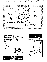
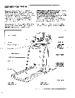
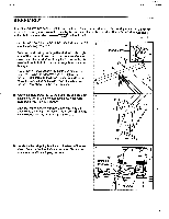
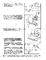
ASSEMBLY Assembly requires two people. Set the treadmill in a cleared area and remove the packing materials. Do not dispose of the packing materials until assembly is completed. Assembly requires the included alien wrench and a phillips screwdriver 4-==r)=0 not included. 1. See the inset drawing. Remove the Base Extensions (76) from the packing materials. Refer to the drawing on page 6 and identify the right side of the treadmill. With the help of a second person, carefully lay the treadmill on its right side; do not lay the treadmill on its left side or the storage latch may be damaged. Firmly slide a Base Extension (76) into one side of the Base (86). Using the Allen Wrench (89), tighten an Extension Bolt (13) into the Base Extension and the Base. While the treadmill is on its side, attach the other Base Extension (not shown) in the same manner. 76 Packing Materials 13 89 86 76 2. Attach six Base Pads (43) to the Base (86) and the Base Extensions (76) in the indicated locations. Note: One 2 extra Base Pad may beincluded. With the help of a second perton, carefully raise the treadmill to theArpright position so the Base (86) and.the Base Extensions (76) are resting on the floor. 76 86 43 86 76 3. Locate the two shipping brackets on the back of the tele- vision. Remove the four indicated screws. Discard the 3 four screws and the shipping brackets. 0 Shipping Brackets Screws 7
-
 1
1 -
 2
2 -
 3
3 -
 4
4 -
 5
5 -
 6
6 -
 7
7 -
 8
8 -
 9
9 -
 10
10 -
 11
11 -
 12
12 -
13
-
14
-
15
-
16
-
17
-
18
-
19
-
20
-
21
-
22
-
23
-
24
-
25
-
26
-
27
-
28
-
29
-
30
-
31
-
32
-
33
-
34
-
35
-
36
 |
 |
