ProForm 820 Elliptical User Manual - Page 7
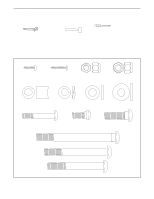
Handlebar Leg with two M8 x 45mm Button Bolts 50
 |
View all ProForm 820 Elliptical manuals
Add to My Manuals
Save this manual to your list of manuals |
Page 7 highlights
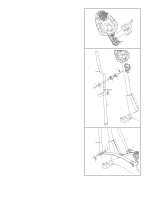
5. The Console (5) requires four "D" batteries (not included); alkaline batteries are recommended. Pull the bat- 5 tery drawer open. Insert four batteries into the battery drawer. Make sure that the batteries are oriented as shown by the diagram inside the battery drawer. Close the battery drawer. Note: When the batteries are installed correctly, the fan will turn on for a moment. 5 Batteries 6. Identify the Left Handlebar (9), which is marked with a sticker. Insert the Left Handlebar into one of the Handlebar Legs (79); make sure that the Handlebar Leg is turned so the hexagonal holes are on the indicated side. Attach the Left Handlebar to the Handlebar Leg with two M8 x 45mm Button Bolts (50) and two M8 Nylon Locknuts (46). Make sure that the Nylon Locknuts are inside of the hexagonal holes. Do not fully tighten the Button Bolts yet. Apply a small amount of the included grease to the left and right axles on the Upright (2). Carefully slide an Upright Spacer (26), a Handlebar Spacer (25), the Left Handlebar (9), and a Handlebar Cap (23) onto the left axle on the Upright (2) as shown. Slide an M10.3 Black Washer (53) onto an M8 x 19mm Shoulder Screw (22), and tighten the Shoulder Screw into the axle. Attach the Right Handlebar and the other Handlebar Leg (not shown) in the same way. 6 9 53 22 23 50 Battery Drawer Grease 2 26 25 46 Hexagonal Holes 79 7. Hold the lower end of the left Handlebar Leg (79) inside of the left Front Flex Bracket (17). Apply a small amount of grease to an M10 x 78mm Button Bolt (27). Attach the left Handlebar Leg to the left Front Flex Bracket with the Button Bolt, two M10 Washers (38), and an M10 Nylon Locknut (29). Do not overtighten the Nylon Locknut; the left Handlebar Leg must be able to pivot freely. Attach the right Handlebar Leg (79) to the right Front Flex Bracket (17) in the same way. Refer to step 6. Tighten the M8 x 45mm Button Bolts (50) in the Handlebar Legs (79). Refer to step 3. Tighten the M10 x 88mm Button Bolt (63). 7 79 29 38 38 27 17 Grease 79 17 7
-
 1
1 -
 2
2 -
 3
3 -
 4
4 -
 5
5 -
 6
6 -
 7
7 -
 8
8 -
 9
9 -
 10
10 -
 11
11 -
 12
12 -
13
-
14
-
15
-
16
-
17
-
18
-
19
-
20
-
21
-
22
-
23
-
24
 |
 |
