ProForm 965 R User Manual - Page 5
Reed Switch Wire 13 or the Resistance Cable
 |
View all ProForm 965 R manuals
Add to My Manuals
Save this manual to your list of manuals |
Page 5 highlights
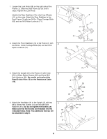
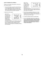
1. Loosen the Lock Knob (68) on the right side of the 1 Frame (1). Slide the Seat Frame (3) out until it stops. Tighten the Lock Knob. Identify the Rear Stabilizer (73), which has Wheels (41) on the ends. Attach the Rear Stabilizer to the Seat Frame (3) with two M10 x 70mm Carriage Bolts (62) and two M10 Nylon Locknuts (71). 68 1 71 73 41 2. Attach the Front Stabilizer (72) to the Frame (1) with 2 two M10 x 70mm Carriage Bolts (62) and two M10 Nylon Locknuts (71). 72 62 3 71 62 1 3. Attach the Upright (2) to the Frame (1) with three 3 M10 x 25mm Button Screws (25) and three M10 Split Washers (26). Be careful not to pinch the Reed Switch Wire (13) or the Resistance Cable (10). 4. Attach the Handlebar (4) to the Upright (2) with two M6 x 25mm Hex Screws (14) and two M6 Split Washers (67), but do not tighten the Screws yet. Make sure that the Screws are threaded into the indicated holes. Note: Two additional Screws will be attached in step 6. 4 67 14 2 71 2 26 25 10 25 26 25 13 1 14 67 4 5
-
 1
1 -
 2
2 -
 3
3 -
 4
4 -
 5
5 -
 6
6 -
 7
7 -
 8
8 -
 9
9 -
 10
10 -
 11
11 -
12
-
13
-
14
-
15
-
16
 |
 |
