ProForm Activator V5 English Manual - Page 10
the Upper Upright.
 |
View all ProForm Activator V5 manuals
Add to My Manuals
Save this manual to your list of manuals |
Page 10 highlights
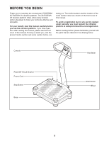
8. Remove the four M4 x 12mm Self-tapping 8 Screws (27) from the back of the Console (3). Set the Self-tapping Screws aside until step 11. 3 27 27 9. Attach the back of the Console (3) to the Upper Upright (36) with two M4 x 16mm Patch Screws 9 (26). Do not tighten the Patch Screws yet. 36 3 26 10. While a second person holds the front of the Console (3) near the Upper Upright (36), con- 10 nect the console ground wire to the Ground Wire (41). Next, connect the console wire to the Wire Harness (43). Then, insert the wires into the Upper Upright. 3 Console Wire 43 36 Console Ground Wire 41 10
-
 1
1 -
2
-
3
-
4
-
 5
5 -
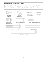 6
6 -
 7
7 -
 8
8 -
 9
9 -
 10
10 -
 11
11 -
 12
12 -
 13
13 -
 14
14 -
 15
15 -
16
-
17
-
18
-
19
-
20
 |
 |

9.
Attach the back of the Console (3) to the Upper
Upright (36) with two M4 x 16mm Patch Screws
(26).
Do not tighten the Patch Screws yet.
9
36
3
26
10. While a second person holds the front of the
Console (3) near the Upper Upright (36), con-
nect the console ground wire to the Ground
Wire (41). Next, connect the console wire to the
Wire Harness (43). Then, insert the wires into
the Upper Upright.
10
3
41
Console
Ground Wire
36
Console
Wire
43
10
8.
Remove the four M4 x 12mm Self-tapping
Screws (27) from the back of the Console (3).
Set the Self-tapping Screws aside until step
11.
8
27
27
3