ProForm C500 Treadmill English Manual - Page 7
end. Hold the Right Upright against the Upright Base - treadmills
 |
View all ProForm C500 Treadmill manuals
Add to My Manuals
Save this manual to your list of manuals |
Page 7 highlights
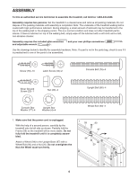
2. See drawing 2a. Identify the Right Upright (95) and the Left Upright (92); note the orientations of the posts on the Uprights. See drawing 2b. Hold the Right Upright (95) near the Upright Base (97), and orient the Right Upright as shown. Make sure that the Right Upright bends in the direction shown. Straighten the Wire Harness (74), and feed it into the lower end of the Right Upright (95) and out of the upper end. Hold the Right Upright against the Upright Base (97). Make sure that no wires are pinched. Hand tighten two Upright Bolts (80) with Upright Star Washers (4) into the bottom of the Upright Base and the lower end of the Right Upright. Do not tighten the Upright Bolts yet. With the help of a second person, carefully tip the treadmill onto its right side. Attach the Left Upright (92) as described above. Note: There is not a wire harness on the left side. Attach the other Wheel (not shown) to the Upright Base (97) as described in step 1. With the help of a second person, carefully lower the treadmill so the Uprights (92, 95) are in a vertical position. 2a 95 Posts 92 2b 74 97 80 4 Bend 95 3. Have a second person hold the Pulse Bar Top (71) between the Uprights (95, 92). See inset drawing 3a. Locate the ground wire on the right end of the Pulse Bar Top. Insert the ground wire through the indicated slot in the post on the Right Upright. See drawing 3b. Locate the pulse wire on the left end of the Pulse Bar Top. Insert the pulse wire into the side of the Left Upright and out of the top as shown. Next, attach the Pulse Bar Top (71) to the posts on the Uprights (95, 92) with two Screws (78). Make sure that the Screws are in the holes shown. As you tighten the Screws, press the ends of the Pulse Bar Top against the posts. Make sure that no wires are pinched. 3a 3b Slot 71 Pulse Wire Ground Wire Posts 78 78 95 92 4. Attach the ring on the end of the ground wire to the indicated hole in the post on the Right Upright (95) with a 4 Silver Ground Screw (23). Make sure that the ring is turned as shown and that the ground wire is routed above or below the head of the indicated Screw (78). Insert the excess wire into the indicated slot in the post on the Right Upright. Slot 78 Ground Wire 23 95 Post 7
-
 1
1 -
 2
2 -
 3
3 -
 4
4 -
 5
5 -
 6
6 -
 7
7 -
 8
8 -
 9
9 -
 10
10 -
 11
11 -
 12
12 -
13
-
14
-
15
-
16
-
17
-
18
-
19
-
20
-
21
-
22
-
23
-
24
-
25
-
26
-
27
-
28
-
29
-
30
 |
 |
