ProForm Edge 3001 English Manual - Page 11
indicator lights
 |
View all ProForm Edge 3001 manuals
Add to My Manuals
Save this manual to your list of manuals |
Page 11 highlights
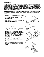
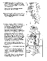
.repetitions and sets are completed, the flashing indicator will darken. Do as many of the indicated exercises as desired. When you have completed the desired exercises for the first muscle group, press on the next muscle group that you want to exercise. Do the indicated exercises as described above. Continue selecting muscle groups until your workout is completed. USING THE MANUAL MODE Press the MANUAL key. The indicator on the MANUAL key will light. One indicator will light on the lower half of the console. Press the NEXT key repeatedly until the indicator lights on the first exercise that you want to do. Press the WEIGHT switch to select a resistance setting as described above for the first exercise. The SETS and REPS displays will show the number of sets and repetitions you should do. As you exercise, the console will count down the repetitions and sets you have completed. When all repetitions and sets are completed, press the NEXT key repeatedly to select the next exercise that you want to do. Continue in this manner until your workout is completed. TURNING THE POWER OFF If the console Is not used for 71/2 minutes, the power will turn off automatically. (See TURNING THE POWER ON.) Unplug the transformer on the power cord when you are finished exercising. USING THE STEPPER The stepper features precision resistance cylinders for long life. It is recommended that the floor beneath the stepper be covered-a small amount of oil leakage is normal for hydraulic cylinders. The resistance of the Pedals (58, 59) can be changed by moving the hooks on the Resistance Cylinders (36) b.N.0 %/111VolVti "...A.... •711NonQUI 4UVi at- U IG r o-uJc-1u- . • •-i- - bUI As_ _ 11111421 II IC hooks are fully inserted into the slotted brackets under the Pedals, and that the hooks are in the same slots under both Pedals. WARNING: The Resistance Cylinders become very hot during use. Allow the Resistance Cylinders to cool before touching them. 36 59 58 Slotted Brackets ATTACHING AND REMOVING THE SEAT FRAME The Seat Frame (43) should be attached as described in assembly step 13 on page 9. To remove the Seat Frame, remove the Hairpin Cotter (11) from the Clevis Pin (12). While holding the Seat Frame remove the Clevis Pin. Lift the Seat Frathe from the Frame (40). Holes To adjust the height of the Seat Frame (43), first remove 12 11 the Seat Frame as described above. Align the hole in the Seat Frame with either the high or low hole in the Frame (40). Insert the Clevis Pin into the Seat Frame and Frame. Insert the Hairpin Cotter (11) into the Clevis Pin. 11
-
 1
1 -
2
-
3
-
4
-
5
-
 6
6 -
 7
7 -
 8
8 -
 9
9 -
 10
10 -
 11
11 -
 12
12 -
 13
13 -
 14
14 -
 15
15 -
 16
16
 |
 |
