ProForm Fusion 6.5 Lx English Manual - Page 8
the M10 Nylon Locknut 108.
 |
View all ProForm Fusion 6.5 Lx manuals
Add to My Manuals
Save this manual to your list of manuals |
Page 8 highlights
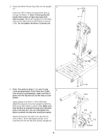
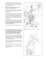
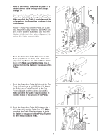
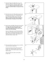
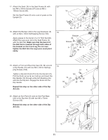
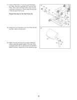
7. Refer to the CABLE DIAGRAM on page 17 to 7 ensure correct cable routing during steps 7 through 14. 66 Use the wire in the Left Press Arm (7) to pull the Press Arm Cable (66) up through the Press Arm. Make sure that the Cable is routed around the pulleys above the Press Arm as shown in the inset drawing. Hold a 4" Pulley (42) over the Press Arm Cable (66). Attach the Pulley inside the Swivel Arm (26) with an M10 x 50mm Button Bolt (88), two M10 Washers (105), two 16mm x 6mm Spacers (11), and an M10 Nylon Locknut (108). 7 108 11 105 42 66 26 88 11 105 8. Route the Press Arm Cable (66) over a 3 1/2" 8 Pulley (43). Attach the Pulley and a Cable Trap (47) to the Top Frame (12) with an M10 x 40mm Screw (97). Make sure that the Cable Trap is oriented to hold the Cable in the groove of the Pulley. 12 66 47 43 97 9. Route the Press Arm Cable (66) through the Top 9 Cover (24) and over a 3 1/2" Pulley (43). Attach the Pulley and a Cable Trap (47) to the Top Frame (12) with an M10 x 40mm Screw (97). Make sure that the Cable Trap is oriented to hold the Cable in the groove of the Pulley. 10. Route the Press Arm Cable (66) between the 3 10 1/2" Pulley (43) and the Cable Trap (47). Make sure that the Cable Trap is oriented to hold the Cable in the groove of the Pulley. Tighten the M10 Nylon Locknut (108). 24 12 66 43 47 97 66 43 108 47 8
-
 1
1 -
2
-
 3
3 -
 4
4 -
 5
5 -
 6
6 -
 7
7 -
 8
8 -
 9
9 -
 10
10 -
 11
11 -
 12
12 -
 13
13 -
14
-
15
-
16
-
17
-
18
-
19
-
20
-
21
-
22
-
23
-
24
 |
 |
