ProForm Power 575i Instruction Manual - Page 12
not overtighten the #10 x 3/4 Screws 9.
 |
View all ProForm Power 575i manuals
Add to My Manuals
Save this manual to your list of manuals |
Page 12 highlights
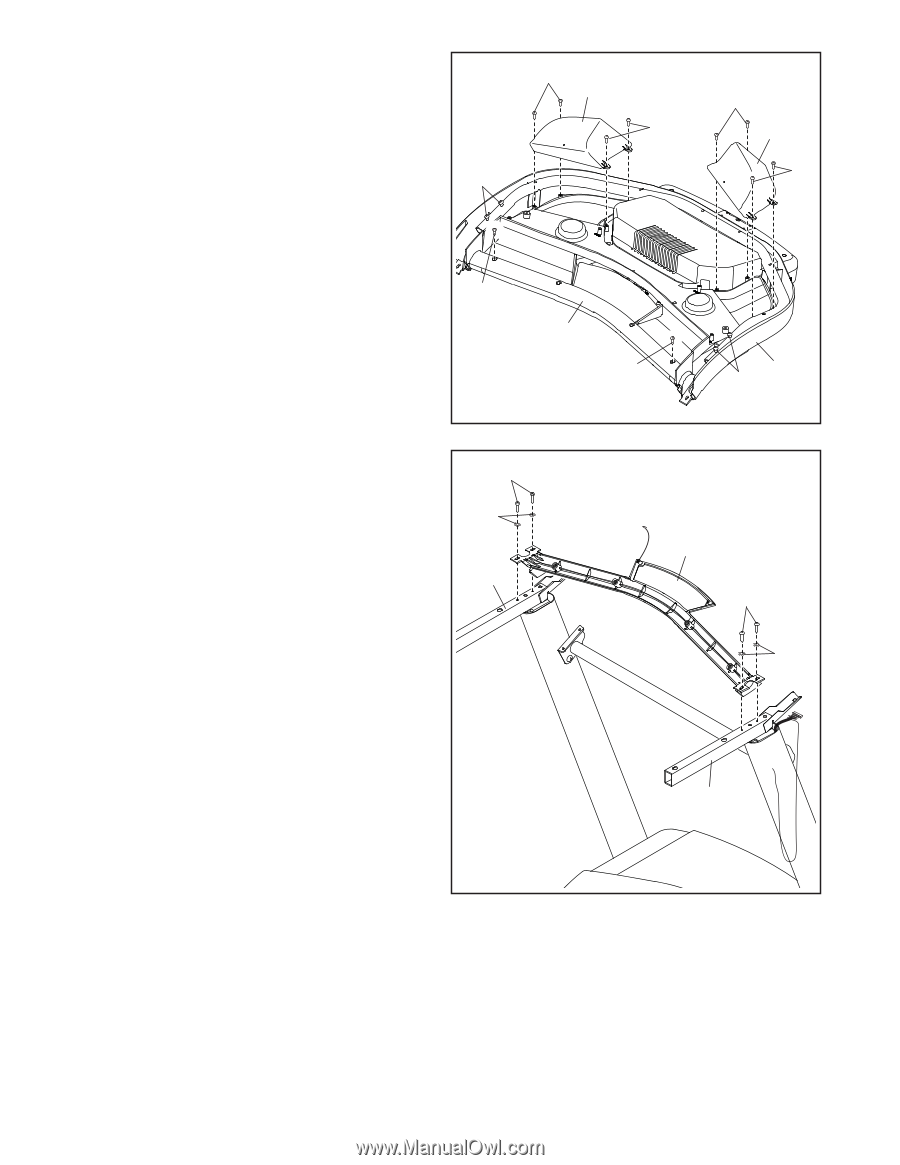
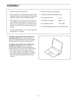
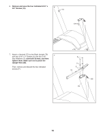
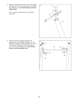
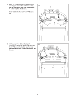
10. Set the Console Base (74) face down on a soft surface to avoid scratching the Console Base. 10 Remove and discard the two indicated screws (G). Then, remove the Pulse Crossbar (75). Next, identify the Left and Right Trays (85, 86). Attach the Trays to the Console Base (74) with 13 eight #8 x 1/2" Screws (10); do not overtighten the Screws. Then, remove and save the four indicated 5/16" x 3/4" Screws (13). G 10 86 10 75 G 10 85 10 74 13 11. IMPORTANT: To avoid damaging the Pulse Crossbar (75), do not use power tools and do not overtighten the #10 x 3/4" Screws (9). Orient the Pulse Crossbar (75) as shown. Attach the Pulse Crossbar to the Handrails (72) with four #10 x 3/4" Screws (9) and four #10 Star Washers (8); start all four Screws, and then tighten them. 11 9 8 72 75 9 8 72 12
-
 1
1 -
2
-
3
-
4
-
5
-
6
-
 7
7 -
 8
8 -
 9
9 -
 10
10 -
 11
11 -
 12
12 -
 13
13 -
 14
14 -
 15
15 -
 16
16 -
 17
17 -
18
-
19
-
20
-
21
-
22
-
23
-
24
-
25
-
26
-
27
-
28
-
29
-
30
-
31
-
32
-
33
-
34
-
35
-
36
-
37
-
38
-
39
-
40
 |
 |