ProForm Sport 7.5 Treadmill English Manual - Page 16
a spacer I out of the other end; discard
 |
View all ProForm Sport 7.5 Treadmill manuals
Add to My Manuals
Save this manual to your list of manuals |
Page 16 highlights
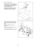
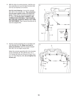
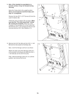
16. Remove the 5/16" Nut (34) and the 5/16" x 2 1/4" Bolt (3) from the bracket on the Latch Crossbar (23). Align the upper end of the Storage Latch (41) with the bracket on the Latch Crossbar (23), and insert the 5/16" x 2 1/4" Bolt (3) through the bracket and the Storage Latch. This will push a spacer (I) out of the other end; discard the spacer. Next, tighten the 5/16" Nut (34) onto the 5/16" x 2 1/4" Bolt (3); do not overtighten the Nut; the Storage Latch (41) must be able to pivot. Then, lower the Frame (56) (see HOW TO LOWER THE TREADMILL FOR USE on page 25). 16 34 I 23 3 56 41 17. Attach the Tablet Holder (36) to the console assembly (E) with four #8 x 1/2" Machine Screws 17 (27); start all four Machine Screws, and then tighten them. Do not overtighten the Machine Screws. 27 36 27 E 18. Make sure that all parts are properly tightened before you use the treadmill. If there are sheets of plastic on the treadmill decals, remove the plastic. To protect the floor or carpet, place a mat under the treadmill. To avoid damage to the console, keep the treadmill out of direct sunlight. Keep the included hex key in a secure place; the hex key is used to adjust the walking belt (see page 27). Note: Extra hardware may be included. 16
-
 1
1 -
2
-
3
-
4
-
5
-
6
-
7
-
8
-
9
-
10
-
 11
11 -
 12
12 -
 13
13 -
 14
14 -
 15
15 -
 16
16 -
 17
17 -
 18
18 -
 19
19 -
 20
20 -
 21
21 -
22
-
23
-
24
-
25
-
26
-
27
-
28
-
29
-
30
-
31
-
32
-
33
-
34
-
35
-
36
 |
 |
