Pyle PDBT35 PDBT35 Manual 1 - Page 1
Pyle PDBT35 Manual
 |
View all Pyle PDBT35 manuals
Add to My Manuals
Save this manual to your list of manuals |
Page 1 highlights
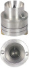
TEMPLATE E 26mm M4mm INSTALLATION INSTRUCTION MODEL PDBT35 If you purchase a Crossover NetworK for your Woofer/Midrange/ Tweeter system you do not need to connect capacitor. If your system does not include a Crossover Network, you must connect capacitor as follows: 1.Connect either end of capacitor to the positive terminal (4.) of speaker. 2.Connect other end of capacitor to the speaker wire harness, Be certain to connect to Positive side of harness, which is the radio out put (+) side. 3.To get best sound performance, it is recommended to use capacitor 3.3 UF 100V for this unit. INSTRUCTIONS D' INSTALLATION MODEL PDBT28 Si vous achetez un Crossover Network pour votre haut-parleur woofer/medium/aigu vous n avez pas besoin de connecter le condensateur. Si votre systeme n' a pas un Crossover network vous devez connecter le condensateur comme suit: 1)Brancher rune des extremites du condensateur a la borne positive(+) du haut parleur. 2)Brancher l'autre extrimite du condensateur au harnais du haut-parleur. Assurez vous de bien connecter le cote sortie radio(+). 3)Pour avoir une meilleur qualite de son, it est recommande dutiliser un condensateur Mylar 3.3 UF 100V pour cette unite. ■ MOUNT ING SURFACE bib V.-MOUNT ING SCREW Itat Rgil`t tf PDBT35 MINT ING SURFACE Midrange ) - 9 - - fP• - ( Tweeter (rQ5sover rwl..work 1.. Capacitor t {' 7:1 :) 13. 7. 1 -rs - SPEAKER • ri) Jr -) 11-1)0 - P; Ti cr.: .{i < - .43 - - I: I C., T. A- - - SpEN-114.{T ) 5' .{ - f Wi - ( Harness ) if "C--..7 0 i•L-E.'19 T ( Radio ) - RH:FE f= i% 7 F Out [AIL - Sfm,nd cjiml i Ly ") i.=3_3111-. INV r'F .P• - tit') t1 .6 -4 -0 P6 L INSTRUCCIONES DE INSTALACION MODELO PDBT35 Si usted compra un crossover para sus bafles o tweeters, no es necesario conectar condensador. Si su sistema no incluye un crossover,usted tendril que conectar un condensador tal y como se describe a continuacion: 1-Conectar cualquier terminal del condensador a la bocina. 2-Conectar la otra terminal del condensador a la bocina. Asegurarse de conectar el positivo del cuadro,el cual es la salida al radio lado (+). 3-Para obtener mejor sonido de su sistema,se recomienda usar (Mylas) capacitores de 3.3 HF-100V para esta unidad. www.pyleaudio.com
-
 1
1
 |
 |
