Pyle PDC22 Owners Manual - Page 2
Front and Rear Panel Layout
 |
View all Pyle PDC22 manuals
Add to My Manuals
Save this manual to your list of manuals |
Page 2 highlights
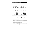
Front and Rear Panel Layout 1. INPUT - 1/4" input connector. 2. PARA OUT - It's parallel output 1/4" jack for passing the input signal through to a stage amplifier or monitor system. 3. ATT Switch - input attenuation, switchable(0dB,-20dB,-40dB) 4. BALANCED OUTPUT - Male XLR connector. 5. GROUND - When engaged, the ground from the PDC22 chassis detaches from the XLR jack. -1-
-
 1
1 -
 2
2 -
 3
3 -
 4
4 -
 5
5 -
 6
6
 |
 |
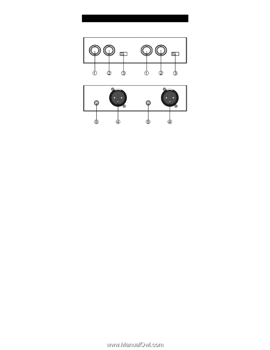
1.
INPUT – 1/4” input connector.
2.
PARA OUT – It’s parallel output 1/4” jack for passing the input signal
through to a stage amplifier or monitor system.
3.
ATT Switch – input attenuation, switchable(0dB,-20dB,-40dB)
4.
BALANCED OUTPUT – Male XLR connector.
5.
GROUND – When engaged, the ground from the PDC22 chassis detaches
from the XLR jack.
Front and Rear Panel Layout
-1-