Pyle PLCM38FRV PLCM38FRV Manual 1 - Page 2
Installation, Wire connection, Red Wire, Yellow Wire, Green, Brown, and White - instructions
 |
View all Pyle PLCM38FRV manuals
Add to My Manuals
Save this manual to your list of manuals |
Page 2 highlights
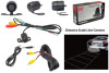
Please read these instructions carefully before installation and use. Installation should be performed by professional staff. 1. Wire connection 2. Installation The camera can be installed in the following ways: A. Bracket-mount (see diagram 1) B. Flush-mount (see diagram 2) C. License plate screw-hole mount (see diagram 3) Car body Car body ( C) Green, Brown, and White: Control Wires (B) Yellow Wire: Video Out (A) Red Wire: Power Connect the 12V power to the red wire (A) using the included 1.2m cable. Use the included 5m cable to connect the yellow wire (B) to your video monitor. For further control, use the control wires (C). Connect power wire, and then connect brown and green wires to reverse the image. Connect brown and white wires first and then connect power wire to show distance lines onscreen. (diagram 1) (diagram 2) (diagram 3) 2.1: Bracket-mount: Install in the rear bumper or on the license plate. Affix with screws. 2.2: Flush-mount: Install by drilling a hole on the rear bumper. 2.3: License plate camera: Mount in the screw hole on the license plate, then affix with a nut. Attention: The camera switch is controlled by the reverse gear shift.
-
 1
1 -
 2
2
 |
 |
