Pyle PLMRWK83WT Instruction Manual - Page 3
Picture 1., Picture 2.
 |
View all Pyle PLMRWK83WT manuals
Add to My Manuals
Save this manual to your list of manuals |
Page 3 highlights
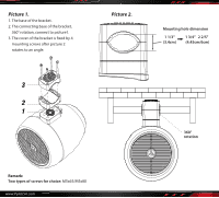
Picture 1. 1. The base of the bracket. 2. The connecting base of the bracket, 360° rotation, connect to picture1. 3. The cover of the bracket is xed by 4 mounting screws after picture 2 rotates to an angle. Picture 2. Mounting hole dimension 1 1/3" (3.4cm) 1 3/4" 2 2/5" (4.45cm/6cm) Remark: Two types of screws for choice: M5x65/M5x80 www.PyleUSA.com 360° rotation
-
 1
1 -
 2
2 -
 3
3 -
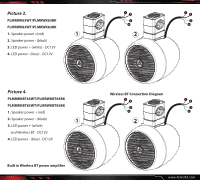 4
4
 |
 |

Mounting hole dimension
1 1/3”
(3.4cm)
(4.45cm/6cm)
1 3/4”
2 2/5”
www.PyleUSA.com
Picture 1.
Picture 2.
1. The base of the bracket.
2. The connecting base of the bracket,
360° rotation, connect to picture1.
3. The cover of the bracket is fixed by 4
mounting screws after picture 2
rotates to an angle.
Remark:
Two types of screws for choice:
M5x65/M5x80
360°
rotation