Pyle PT610 PT610 Manual 1 - Page 4
Installation Guidelines - pro amplifier mixer
 |
View all Pyle PT610 manuals
Add to My Manuals
Save this manual to your list of manuals |
Page 4 highlights
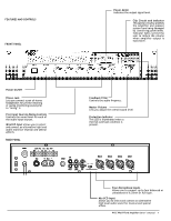
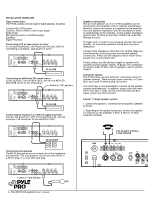
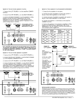
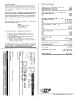
INSTALLATION GUIDELINES Input connections The PT610 accepts a broad range of input sources, including: Compact Disc (CD) player Cassette, Reel-to-Reel or other tape player Radio Tuner Microphones (up to 4 simultaneously) Equalizer Signal Processor Connecting a CD or tape player or tuner In a normal installation, one would use the LINE JACK for connecting a CD player, tape player or tuner FUSE 110 COM 4Ω 8Ω 16Ω 70V 8Ω + 8Ω - GND IN L R OUT LINE CD MIC4 MIC3 MIC2 MIC1 CD PLAYER Connecting an additional CD sound source In this situation, use the MIC4 JACK, and set the MIC4/CD SELECTOR switch to the CD position. Switch in "CD" position. FUSE 110 COM 4Ω 8Ω 16Ω 70V 8Ω + 8Ω - GND IN L R OUT LINE CD MIC4 MIC3 MIC2 MIC1 CD PLAYER Connecting an equalizer or external signal processor Connect the processor's OUT to the amplifier's IN, and the processor's IN connector to the amplifier's OUT. FUSE 110 COM 4Ω 8Ω 16Ω 70V 8Ω + 8Ω - GND IN L R OUT LINE CD MIC4 MIC3 MIC2 MIC1 EQ OR MIXER Connecting microphones The MIC IN jacks permit you to connect up to 4 low impedance microphones. The microphones can be used with either a 6.35mm plug, or a 3-pin XLR type plug. FUSE 110 COM 4Ω 8Ω 16Ω 70V 8Ω + 8Ω - GND IN L R OUT LINE CD MIC4 MIC3 MIC2 MIC1 6.3mm or 3-pin XLRJack MIC 2 - PYLE PRO PT610 Amplifier Owner's Manual Speaker connections One or more speakers (4, 8 or 16 Ohm) speakers can be connected to the amplifier with or without transformers. However, before you connect any speakers to the amplifier, the total speaker impedance must be calculated in order to avoid damage to the amplifier. A total speaker impedance greater than 16 Ohms or less than 4 Ohms can cause this damage to occur. To begin with, in order to ensure equal volume from each speaker, all connected speakers should have the same impedance. A proper total impedance within the 4 to 16 Ohm range can be acheived by combining series and parallel speaker connections. Please see the diagrams which follow which explain how to accomplish this. Finally, always use the shortest length of speaker wire possible of proper gauge. Usually, 18 gauge wire is adequate for lengths under 25 feet, while 16 gauge is used for greater lengths. Connector options The PT-610 offers several different connection points for speaker hookups. These include screw terminals, a 6.3mm jack, and a pair of banana plug connectors. It is not proper or recommended to connect all the speaker outputs simultaneously. In addition, please note that when the 6.3mm jack is used, all the screw terminal and RCA signal outputs are disconnected. System 1: Single speaker system 1. Connect the speaker (-) terminal to the amplifier COMMON terminal. 2. Depending on the speaker being used, connect the speaker (+) terminal to the amplifier 4 Ohm, 8 Ohm or 16 Ohm amplifier terminal. THIS EXAMPLE SHOWS A 4 OHM SPEAKER FUSE 110 COM 4Ω 8Ω 16Ω 70V 8Ω + 8Ω - GND IN OUT LINE C
-
 1
1 -
 2
2 -
 3
3 -
 4
4 -
 5
5 -
 6
6
 |
 |
