RCA 25201RE1 User Guide - Page 1
RCA 25201RE1 - ViSYS Corded Phone Manual
 |
UPC - 044319805772
View all RCA 25201RE1 manuals
Add to My Manuals
Save this manual to your list of manuals |
Page 1 highlights
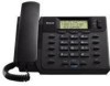
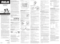
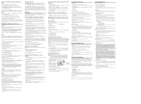
2-Line Intercom Speakerphone User's Guide Please read this manual before operating product for the first time. Model 25201 Equipment Approval Information Your telephone equipment is approved for connection to the Public Switched Telephone Network and is in compliance with parts 15 and 68, FCC Rules and Regulations and the Technical Requirements for Telephone Terminal Equipment published by ACTA. 1. Notification to the Local Telephone Company On the bottom of this equipment is a label indicating, among other information, the US number and Ringer Equivalence Number (REN) for the equipment. You must, upon request, provide this information to your telephone company. The REN is useful in determining the number of devices you may connect to your telephone line and still have all of these devices ring when your telephone number is called. In most (but not all) areas, the sum of the RENs of all devices connected to one line should not exceed 5. To be certain of the number of devices you may connect to your line as determined by the REN, you should contact your local telephone company. A plug and jack used to connect this equipment to the premises wiring and telephone network must comply with the applicable FCC Part 68 rules and requirements adopted by the ACTA. A compliant telephone cord and modular plug is provided with this product. It is designed to be connected to a compatible modular jack that is also compliant. See installation instructions for details. Notes • This equipment may not be used on coin service provided by the telephone company. • Party lines are subject to state tariffs, and therefore, you may not be able to use your own telephone equipment if you are on a party line. Check with your local telephone company. • Notice must be given to the telephone company upon permanent disconnection of your telephone from your line. • If your home has specially wired alarm equipment connected to the telephone line, ensure the installation of this product does not disable your alarm equipment. If you have questions about what will disable alarm equipment, consult your telephone company or a qualified installer. US Number is located on the cabinet bottom REN number is located on the cabinet bottom 2. Rights of the Telephone Company Should your equipment cause trouble on your line which may harm the telephone network, the telephone company shall, where practicable, notify you that temporary discontinuance of service may be required. Where prior notice is not practicable and the circumstances warrant such action, the telephone company may temporarily discontinue service immediately. In case of such temporary discontinuance, the telephone company must: (1) promptly notify you of such temporary discontinuance; (2) afford you the opportunity to correct the situation; and (3) inform you of your right to bring a complaint to the Commission pursuant to procedures set forth in Subpart E of Part 68, FCC Rules and Regulations. The telephone company may make changes in its communications facilities, equipment, operations or procedures where such action is required in the operation of its business and not inconsistent with FCC Rules and Regulations. If these changes are expected to affect the use or performance of your telephone equipment, the telephone company must give you adequate notice, in writing, to allow you to maintain uninterrupted service. Visit the RCA web site at www.rca.com Please do not send any products to the Indianapolis address listed in this manual or on the carton. This will only add delays in service for your product. Model 25201 00023042 (Rev. 0 Dom E) 07-51 Printed in China Thomson Inc. 101 West 103rd St. Indianapolis, IN 46290-1102 © 2007 Thomson Inc. Trademark(s) ® Registered Marca(s) Registrada(s) Interference Information This device complies with Part 15 of the FCC Rules. Operation is subject to the following two conditions: (1) This device may not cause harmful interference; and (2) This device must accept any interference received, including interference that may cause undesired operation. This equipment has been tested and found to comply with the limits for a Class B digital device, pursuant to Part 15 of the FCC Rules. These limits are designed to provide reasonable protection against harmful interference in a residential installation. This equipment generates, uses, and can radiate radio frequency energy and, if not installed and used in accordance with the instructions, may cause harmful interference to radio communications. However, there is no guarantee that interference will not occur in a particular installation. If this equipment does cause harmful interference to radio or television reception, which can be determined by turning the equipment off and on, the user is encouraged to try to correct the interference by one or more of the following measures: • Reorient or relocate the receiving antenna (that is, the antenna for radio or television that is "receiving" the interference). • Reorient or relocate and increase the separation between the telecommunications equipment and receiving antenna. • Connect the telecommunications equipment into an outlet on a circuit different from that to which the receiving antenna is connected. If these measures do not eliminate the interference, please consult your dealer or an experienced radio/television technician for additional suggestions. Also, the Federal Communications Commission has prepared a helpful booklet, "How To Identify and Resolve Radio/TV Interference Problems." This booklet is available from the U.S. Government Printing Office, Washington, D.C. 20402. Please specify stock number 004-000-00345-4 when ordering copies. Notice: The changes or modifications not expressly approved by the party responsible for compliance could void the user's authority to operate the equipment. Hearing Aid Compatibility This telephone system meets FCC standards for Hearing Aid Compatibility. Licensing Licensed under US Patent 6,427,009. Introduction CAUTION: When using telephone equipment, there are basic safety instructions that should always be followed. Refer to the IMPORTANT SAFETY INSTRUCTIONS provided with this product and save them for future reference. Short Glossary of Terminology Used in this Manual Hook switch. The part of the phone that pops up to activate the phone line when the handset is lifted from the base. Line indicator. The light located next to each of the line buttons; it shows you the status of each line. Off-hook. A term used to describe the phone in its active mode when the handset is off of the base cradle or a line button, along with the Speaker button, is pressed. On-hook. A term used to describe the phone in an inactive mode. Before You Begin Parts Checklist Make sure your package includes the following items: Base Handset Handset cord Desktop pedestal 4-wire telephone line cord Modular Jack Requirements To properly connect your phone to your Wall plate telephone lines, you should identify the type of wall jack(s) you have. You will need an RJ11C (for a single line) or a RJ14C (for two lines) type modular phone jack, which might Modular telephone line jack look like the one pictured here. If you don't have either modular jack, call your local phone company to find out how to get one installed. Important Installation Information • Never install telephone wiring during a lightning storm. • Never touch uninsulated telephone wires or terminals, unless the telephone line has been disconnected at the network interface. • Use caution when installing or modifying telephone lines. • Never install telephone jacks in wet locations unless the jack is specifically designed for wet locations. • Temporarily disconnect any equipment connected to the phone, such as faxes, other phones, or modems. Base Layout Display Delete (button) Memory (buttons) Review (button) Menu (button) Store (button) Mute (button) Mute (indicator) *Tone (button) Volume (button) Redial/Pause (button) Speaker (indicator) Speaker (button) Dial (button) Conference (button) Line 2 (Indicator) Line 2 (button) Line 1 (button) Mic Hold (button) Line 1 (Indicator) Flash/Exit (button) Installation & Setup CAUTION: Disconnect the phone cord from the wall outlet before installing or replacing the batteries. Installing the Batteries Your Caller ID phone uses 4 AA-size alkaline batteries for receiving and storing Caller ID records and for storing the numbers you use for memory dialing, pulse dialing, redial, and predial functionality. 1. Release latch on battery compartment and remove cover. 2. Insert 4 AA-size alkaline batteries as shown on the diagram in the battery compartment. 3. Snap the battery compartment door back into place and replace the mounting bracket. 4. If the line cord was previously connected, re-attach it to the unit and check your memory locations. NOTE: If the low battery icon appears in the display, you need to replace the batteries. It is important that you replace the batteries as soon as possible in order to maintain Caller ID operation. IMPORTANT: If you are not going to use the telephone for more than 30 days, remove the batteries because they may leak and damage the unit. Installation Desktop Installation To attach the desktop pedestal: NOTE: Ensure the handset hook is in the DESK position. Adjust it by pushing up and out of the slot on the base with your thumb, rotate the hook 180°, and replace it back in the slot. FIGURE 1 One dual-line jack or one single-line wall phone jack FIGURE 2 Two single-line wall phone jacks To connect LINES 1 + 2: There are two possible connections. Refer to Figure 1 if you have one single line (RJ11C) phone jack or one dual-line (RJ14C) phone jack. 1. Connect one end of either straight telephone line cord to the jack marked Line 1+2 on the back of the base. 2. Connect the other end to the single-line or dual-line wall phone jack. NOTE: If you connect the telephone line cord to the single-line (RJ11C) wall phone jack, you will only be able to use one telephone line (either Line 1 or Line 2) but not both lines simultaneously. Refer to Figure 2 if you have two single-line (RJ11C) phone jacks. 1. Connect one end of either straight telephone line cord to the jack marked Line 1+2 on the back of the base. 2. Connect one end of the other straight telephone line cord to the jack marked Line 2 on the back of the base. 3. Connect the other end of each straight telephone line cord to the two single line wall phone jack. 4. Plug one end of the coiled handset cord into the handset and the opposite end into the base. 5. Set the Ringer Line 1 and Ringer Line 2 volume switches located at the back of the base to the desired loudness. OFF - Telephone will not ring. LO - Sound will be lowest. HI - Sound will be loudest. 6. Press the Line 1 button if the Line 1 telephone cord is connected. Otherwise, press Line 2. 7. The unit is properly installed if you pick up the handset and hear the dial tone. Otherwise, recheck all installation steps. To detach the desktop pedestal: Wall Mount Installation Your speakerphone can also be mounted on a wall plate (not included). NOTE: To prevent the handset from falling out of the cradle while the phone is hanging on the wall, you must set the handset hook (located on the base) in the WALL position. You will also need to remove the desktop pedestal if attached. To connect LINES 1 + 2: There are two possible connections. Refer to Figure 1 at beginning of Installation section if you have one single line (RJ11C) phone jack or one dual-line (RJ14C) phone jack. 1. Connect one end of either straight telephone line cord to the jack marked Line 1+2 on the back of the base. 2. Connect the other end to the single-line or dual-line wall phone jack. NOTE: If you connect the telephone line cord to the single-line (RJ11C) wall phone jack, you will only be able to use one telephone line (either Line 1 or Line 2) but not both lines simultaneously. Refer to Figure 2 at beginning of Installation section if you have two single-line (RJ11C) phone jacks. 1. Connect one end of either straight telephone line cord to the jack marked Line 1+2 on the back of the base. 2. Connect one end of the other straight telephone line cord to the jack marked Line 2 on the back of the base. 3. Connect the other end of each straight telephone line cord to the two single line wall phone jack. 4. Slip the mounting holes over the wall plate posts and firmly slide the unit down into place (wall plate not included). 5. Plug one end of the coiled handset cord into the handset and the opposite end into the base. 6. Set the Ringer Line 1 and Ringer Line 2 volume switches located at the back of the base to the desired loudness. OFF - Telephone will not ring. LO - Sound will be lowest. HI - Sound will be loudest. 7. Press the Line 1 button if the Line 1 telephone cord is connected. Otherwise, press the Line 2 button. 8. The unit is properly installed if you pick up the handset and hear the dial tone. Otherwise, recheck all installation steps. Data Port This phone is equipped with a Line 2 jack for you to connect an auxiliary phone device, such as a fax machine, computer modem, answering machine, or even a cordless phone. You can install the phone as described in "Two Lines on a Single Modular Jack", then you can use the Line 2 jack to connect your fax machine and receive faxes on the phone number for Line 2. Setting Up the Caller ID Menu You should not plug the telephone into the modular jack while setting up the Caller ID menu. 1. Press the Menu button to enter the menu feature configuration mode. # 1. >ENG FRA ESP (CID language default English) # 2. CONTRAST (default level is 3). # 3. LOCAL AREA CODE # 4. TONE/PULSE (Default is tone dialing). 2. Press the Menu button to scroll through the 4 menu screens. 3. Use the Review 5 or 6 buttons to select the desired setting. NOTE: You have 20 seconds following an entry before the phone returns to the Summary Screen. Setting the Display Language This adjustment changes the Caller ID prompts to be displayed in English, French, or Spanish. 1. Press the Menu button until ENG FRA ESP shows in the display. 2. Use the Review 5 or 6 button to select ENG, FRA or ESP. 3. Press the Menu button to save. Setting the Contrast This adjustment allows you to adjust the contrast of the display. 1. Press the Menu button until CONTRAST shows in the display. 2. Use the Review 5 or 6 buttons to select level 1, 2, 3, 4, or 5. 3. Press the Menu button to save. Setting Your Local Area Code The telephone uses the programmed area codes to determine the number format to display when a valid Caller ID signal is received. Numbers that match the local area code are displayed as seven digits and are used for dialing back previous numbers. Entering your local area code will also help you immediately know if the call is local or long distance when viewing the CID records in the display. NOTE: If you make a mistake and want to start over again, press the Delete button to delete all of the digits. 1. Press the Menu button until LOCAL AREA CODE shows in the display. 2. Press the Review 5 button to enter the second and third digit. 3. Press the Review 6 button to enter digit. NOTE: The local area code may also be entered directly by using the number pad. 4. Press the Menu button to save. Setting the Dial Mode This adjustment allows you to select tone (touch-tone) or pulse (rotary) dialing. 1. Press the Menu button until TONE/PULSE shows in the display. 2. Press the Review 5 or 6 buttons to show the current dialing mode. The default is TONE dialing. 3. To change the dialing mode, press the review key. The display alternates between the two modes. 4. Press the Menu button to save. NOTE: The phone will exit set up after 20 seconds if no buttons are pressed. REMINDER: The time and date are programmed automatically when the first Caller ID record is successfully received after set up. Caller ID Features IMPORTANT: In order to use all of the features of this telephone, you must subscribe to two separate services available from your local telephone company: the standard Name/Number Caller ID Service to know who is calling when the phone rings and Caller ID with Call Waiting Service to know who is calling while you are on the phone. Summary Screen The Summary Screen shows the current time, date, and number of new calls to review. It is displayed until any button is pressed. NOTE: The number of new calls is displayed until all new calls have been reviewed. Receiving and Storing Calls This unit receives and displays information transmitted by your local phone company. This information can include the phone number, date, and time; or the name, phone number, date, and time. The unit can store up to 75 calls for later review. When the memory is full, a new call automatically replaces the oldest call in memory. NEW appears in the display for calls received that have not been reviewed. Reviewing Call Records • Press the Review 5 or 6 button to view the call records. • Press the Review 5 button to scroll through the call records from the old one to the next new one. • Press the Review 6 button to scroll through the call records from the new one to the previous one. • When all of the records have been viewed, START/END appears in the display. Deleting Call Records • To delete the record shown in the display, press the Delete button once. • To delete all records while reviewing, press and hold the Delete button for about three seconds. DELETE ALL? appears in the display. Press Delete again to complete. Dialing Back When reviewing Caller ID records, you can dialback the numbers shown on the display by pressing the Dial button. NOTE: If PICKUP PHONE shows in the display, no other changes to the number can be made. The information sent from the telephone company is known to be a valid number for dialing back (used only in very limited areas). Once you pickup the phone, the number is automatically dialed. NOTE: Make sure either line button 1 or 2 is pressed, when the handset is picked-up or the speakerphone is in use. If You Programmed Your Local Area Code In the Set Up Menu 1. Use the Review 5 or 6 button to display the number you want to dial. 2. Press the Dial button. • If you see a number with seven digits (i.e. 555-1234), then the call is from within your area code. However, this does not guarantee the call is a local call. • If you see a number with 11 digits (i.e. 1-234-555-1234), then the call is not from within your area code. NOTE: A timer (10 seconds on-hook and 3 seconds off-hook) located in the upper right side of the display will start, letting you know how much time is left until the unit returns to the Summary Screen. 3. If you are at on-hook and PICKUP OR ADJ displays, you can adjust the phone number format by pressing the Dial button. If the phone is off-hook and ADJUST shows in the display, you can adjust the phone number format by pressing the Dial button. For example, sometimes a 7-digit local number cannot be dialed because it requires a 10-digit or 11-digit format. Press the Dial button repeatedly to scroll through the 7, 10, and 11-digit numbers. 7-digits: 7-digit telephone number (i.e. 555-5555) 10-digits: 3-digit area code + 7-digit telephone number (i.e. 425-555-5555) 11-digits: long distance code 1 + 3-digit area code + 7digit telephone number (i.e. 1-425-555-5555) 4. To dial the displayed number, and the phone is on-hook, pick up the handset or press the Speaker button before the timer reaches 0. If the phone is off-hook, wait until the time reaches 0. NOW DIALING shows in the display and the number is dialed. NOTE: Make sure either the 1 or 2 line button is pressed. If You Did Not Program Your Local Area Code In the Set Up Menu 1. Use the Review 5 or 6 buttons to display the number you want to dial. You will only see 10-digit numbers (i.e. 234- 555-1234). 2. See steps 2 through 4 in the previous section to complete the dialback process. Caller ID Display Messages The following special messages indicate the status of a message or the unit: BLOCKED CALL The caller of the incoming call is registered as "Private Number" and their Caller ID information is withheld. CALL WAITING Indicates a call is waiting on the line. Battery power level is low. NO CALLS The caller memory is empty. START/END You are at the beginning or the end of the Caller ID memory log. UNKNOWN CALLER The incoming call does not have Caller ID service or their service area is not linked to yours. If UNKNOWN CALLER appears along with a calling number, the name information for that number was not available. Speakerphone Basics Speakerphone Location Your phone features a speakerphone for ease of use and convenience during a phone conversation. At any time during a conversation, you can lift the handset to stop using the speakerphone. Likewise, when you are using the handset, press the Speaker button and place the handset in the cradle to switch to the speakerphone. For best speakerphone performance, avoid the following: • Areas with high background noise. (The microphone might pick up these sounds and prevent the speakerphone from going into the receiving mode when you finish talking.) • Surfaces affected by vibration. • Recessed areas such as in a corner, under a cupboard, or next to a cabinet, which can generate an echo effect. Speakerphone Use Note the following guidelines when using the speakerphone: • The speakerphone works similar to a two-way radio in that you can only listen or talk at one time. • Stay reasonably close to the phone so that you can be clearly heard by the person to whom you are talking. • You can adjust the speaker volume by pressing the volume button continuously or pressing the Review 5 or 6 buttons after pressing the Volume button. • The speakerphone indicator light comes on when the speakerphone is in use. NOTE: Batteries must be installed for the speakerphone to operate. Telephone Basics You can use the telephone by speaking into and listening through the handset, or by using the Speakerphone feature. For all operations, either Line 1 or 2 button must be pressed. Do not press both buttons down at the same time. Line Status Indicators This two-line phone is designed for use at multiple stations. The indicator light tells you what is happening on each line. When the And the Icon indicator light is: on the LCD is: It Means: Off Off The line is not in use. Flashing Red Off A call is being received. Green On The line is in use by this phone. Red Flashing A call is on hold. Off Off A parallel phone is using the line. Off Flashing Line not connected. Making a Phone Call 1. Press Line 1 or Line 2 button, and lift the handset or press the Speaker button. Wait for a dial tone. 2. Dial the telephone number you want to call. OR Pre-dial the number, select Line 1 or Line 2, then lift handset or press the Speaker button. 3. Replace the handset in the cradle, or press the Speaker button to hang up. Receiving a Phone Call 1. To answer an incoming call, press the Line button next to the flashing red indicator. 2. Lift the handset or press Speaker to answer the call. 3. Replace the handset in the cradle or press the Speaker button to hang up. Adjusting the Handset and Speakerphone Volume The volume controls for the handset and speakerphone are separate, so you can adjust one without affecting the other. To adjust the handset volume, pick up the handset, press the Volume button continuously or press the Review 5 or 6 buttons after pressing the Volume button. REC (handset receiver) or SPK (speakerphone mode) shows in the display. While using the speakerphone, adjust the speakerphone volume by pressing the Volume button continuously or pressing Review 5 or 6 buttons after pressing the Volume button. Both handset receiver and speakerphone volume level setting will be saved in the unit's memory. Using the Speakerphone To use the speakerphone feature, press a line button and then press the Speaker button. For more information refer to Speakerphone Basics.
-
 1
1 -
 2
2
 |
 |