RCA 26LB30RQD User Manual - Page 8
Safety Strap - wall mount
 |
View all RCA 26LB30RQD manuals
Add to My Manuals
Save this manual to your list of manuals |
Page 8 highlights
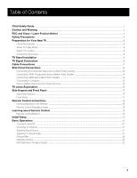
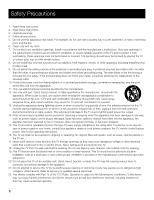
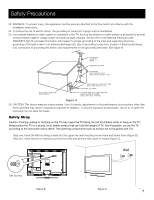
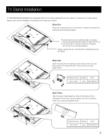
Safety Precautions 23. WARNING: To prevent injury, this apparatus must be securely attached to the floor/wall in accordance with the installation instructions. 24. To reduce the risk of electric shock, the grounding of center pin of plug must be maintained. 25. If an outside antenna or cable system is connected to the TV, be sure the antenna or cable system is grounded to provide some protection against voltage surges and built-up static charges. Section 810 of the National Electrical Code, ANSI/NFPA NO.70, provides information with respect to proper grounding of the mast and supporting structure, grounding of the lead-in wire to an antenna discharge unit, size of grounding conductors, location of antenna discharge unit, connection to grounding electrodes, and requirements for the grounding electrode. (See figure A) ANTENNA LEAD IN W IRE GROUND CLAMP ANTENNA DISCHARGE UNIT (NEC SECTION 810-20) G R O U N D I N G C O N D U C T O RS (NEC SECTION 810-21) GROUND CLAMPS ELECTRIC SERVICE EQUIPMEN T POWER SERVICE GROUNDING E L E C T R O D E S Y S TEM ( N E C A R T 2 5 0 , P A R T H) Figure A 26. CAUTION: This device employs a laser system. Use of controls, adjustments or the performance of procedures other than those specified may result in hazardous exposure to radiation. To prevent exposure to laser beam, do not try to open the enclosure. Do not stare into beam. Safety Strap Caution: Pushing, pulling or climbing on the TV may cause the TV falling. Do not let chlidren climb or hang on the TV. Always place the TV on a sturdy, level, stable surface that can hold the weight of TV. And if possible, secure the TV according to the instruction below (Note: The fastening components such as screws are not supplied with TV). Step one: Insert the M6 mounting screws into the upper two wall mounting screw holes and fasten them (Figure B). Step two: Insert anchors to wall and connect the bolts and anchors with ropes or chains (Figure C). Wall M6 Screws Figure B Figure C 7
-
 1
1 -
2
-
 3
3 -
 4
4 -
 5
5 -
 6
6 -
 7
7 -
 8
8 -
 9
9 -
 10
10 -
 11
11 -
 12
12 -
 13
13 -
14
-
15
-
16
-
17
-
18
-
19
-
20
-
21
-
22
-
23
-
24
-
25
-
26
-
27
-
28
-
29
-
30
-
31
-
32
-
33
-
34
-
35
-
36
-
37
-
38
-
39
-
40
-
41
-
42
-
43
-
44
-
45
-
46
-
47
-
48
-
49
-
50
-
51
 |
 |