RCA ANT3020X Installation Manual: ANT3020X - Page 2
Installation Directions - antenna
 |
UPC - 079000308898
View all RCA ANT3020X manuals
Add to My Manuals
Save this manual to your list of manuals |
Page 2 highlights
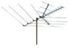
INSTALLATION DIRECTIONS ANT3036W ANT3036X ANT3020X Step 54Connecting Lead-in Cable To The Antenna We recommend RG-6 cable, and, if you prepare your own cable, a quality F-connector. Note: If you prepare your own cable, slide a matching transformer's weatherboot onto the cable before you attach the F-connector. 1. Thread the spade terminal ends of a matching transformer through either slot on the antenna's strain relief tab. Then use the supplied washers and large wing nuts to secure the transformer's leads to the antenna's threaded lead-in terminals marked CONNECT LEAD-IN HERE. 2. Screw the cable's F-connector onto the matching transformer. If you use a prebuilt cable without a weatherboot, cover the connection with weatherproof tape. Otherwise, slip the weatherboot over the connection. Step 74Attaching The Antenna To The Mast We recommend you get the help of another person before you put up the mast or attach your antenna to it. How you set up your mast depends on your specific installation. Refer to the Consumer Product Safety Commission information for recommended methods. 1. With the antenna's support brackets on top of the boom, slide the antenna's mast clamp assembly (or assemblies for models ANT3036X and ANT3036W) over the top of the mast. For models ANT3036X and ANT3036W make sure the main boom is on top with the plastic brackets on top, and the support boom is underneath. 2. Tighten the mast clamp assembly's lock nuts to hold the antenna in place. Do not overtighten the lock nuts. Caution: The crossover wires must not touch the antenna boom, the mast, or each other. If necessary, carefully bend the crossover wires to provide at least 1/2 inch of clearance. Mast Clamp Support Bracket CAUTION WARNING: INSTALLATION OF THIS PRODUCT IS DANGEROUS. FOR YOUR SAFETY, FOLLOW THE INSTALLATION DIRECTIONS. Before You Begin Read this manual and the Consumer Product Safety Commission information. For your safety and convenience, plan each step of the installation and purchase the necessary hardware in advance. The hardware required and the order in which you perform the steps depends on the mounting and connection methods you choose. 4ASSEMBLING THE ANTENNA For outdoor installation, we recommend you assemble the entire antenna on the ground, then mount it on a mast. For attic installation, first measure your attic to make sure the assembled antenna will fit. The assembled antenna might not fit through your attic's entrance, so you might need to perform most of the assembly in the attic. Look at the carton and label to see what model of antenna you have. The steps below apply to all models or, where specified, apply only to models ANT3036X and ANT3036W. Step 14Splinting the Main Boom Sections Together For models ANT3036X and ANT3036W, use the supplied hardware to assemble the main boom sections. If necessary, lift one end of the main boom so the crossover wires reach the threaded posts of the next section. Note: There are no crossover wires over the back section. ►Your antenna may look different than the one shown here. Step 24Mast Clamp Assembly 1. Use the supplied hardware to loosely attach the supplied mast clamp assembly to the main antenna boom. For models ANT3036X and ANT3036W, attach the support boom's mast clamp assembly, facing it the same direction as the main boom's mast clamp assembly. 2. Press the supplied large end plugs into the ends of the main antenna boom and the model ANT3036X and ANT3036W support boom. Step 34Support Boom Assembly 1. For models ANT3036X and ANT3036W, align the support boom's straps and mast clamp with the main boom's support strap holes and mast clamp. 2. Attach the support straps to the main boom using the two supplied 1½- inch screws and large wing nuts. ►Your antenna may look different than the one shown here. Step 44UHF Dipole and Isolation Network Assembly 1. For models ANT3036X and ANT3036W, pull the two halves of the UHF dipole away from the main boom until they lock into the support bracket. 2. Place each half's unattached end over one of the antenna's lead-in terminals (one for each half of the UHF bowtie on each side of the boom). Note: Both bars of the isolation network should remain parallel to the main boom. ►Your antenna may look different than the one shown here. Main Boom Step 64Unfolding The Antenna Elements 1. Hold each UHF wing boom and turn its elements until they snap squarely into place (perpendicular to the wing booms). 2. Press the supplied small end plugs into the ends of the wing booms. 3. Fold out the wing booms and secure them into position using the two supplied 1¼-inch screws and wing nuts. 4. Hold the main boom's elements near the pivot points and pull them away from the boom until they snap into the locking support brackets. Note: You may wait to unfold the elements until you get the antenna up on the roof or in your attic. Caution: Do not pull the elements near their outer ends or you could damage them. Main Boom Support Boom ►Your antenna may look different than the one shown here. 3. Set up the mast, then rotate it so the antenna's shortest elements point toward the stations you want to receive. Then secure the mast into position. Note: You can also put the antenna in an attic space. You can mount it from a rafter or simply place the antenna on the attic floor. However, we recommend that you use mounting hardware for the most secure installation. Step 84Routing The Cable To Your TV/FM Receiver 4 Use plastic tape to secure the coaxial cable to the mast at 3-foot intervals. 4 Use coaxial nail clips every few feet to secure the cable between the mast and where the cable enters the house. 4 Use a 75-ohm grounding block at the point where the coaxial cable enters the house. Read the Consumer Product Safety Commission information for grounding instructions. 4 Use a drip-loop before the cable enters the house. 4 Use a wall-thru tube to neatly route the coaxial cable thru the walls. 4 Use only the length of coaxial cable that your installation needs. Do not coil extra cable behind receiver. Instead, cut it to the correct length. 412 MONTH LIMITED WARRANTY Audiovox Electronics Corporation (the "Company") warrants to the original retail purchaser of this product that should this product or any part thereof, under normal use and conditions, be proven defective in material or workmanship within 12 months from the date of original purchase, such defect(s) will be repaired or replaced (at the Company's option) without charge for parts and repair labor. To obtain repair or replacement within the terms of this Warranty, the product along with any accessories included in the original packaging is to be delivered with proof of warranty coverage (e.g. dated bill of sale), specification of defect(s), transportation prepaid, to the Company at the address shown below. Do not return this product to the Retailer. This Warranty is not transferable and does not cover product purchased, serviced or used outside the United States or Canada. The warranty does not extend to the elimination of externally generated static or noise. This Warranty does not apply to costs incurred for installation, removal or reinstallation of the product, or, if in the Company's opinion, the product has been damaged through acts of nature, alteration, improper installation, mishandling, misuse, neglect, or accident. This warranty does not cover damage caused by an AC adapter not provided with the product. THE EXTENT OF THE COMPANY'S LIABILITY UNDER THIS WARRANTY IS LIMITED TO THE REPAIR OR REPLACEMENT PROVIDED ABOVE AND, IN NO EVENT, SHALL THE COMPANY'S LIABILITY EXCEED THE PURCHASE PRICE PAID BY PURCHASER FOR THE PRODUCT. This Warranty is in lieu of all other express warranties or liabilities. ANY IMPLIED WARRANTIES, INCLUDING ANY IMPLIED WARRANTY OF MERCHANTABILITY OR FITNESS FOR A PARTICULAR PURPOSE, SHALL BE LIMITED TO DURATION OF THIS WARRANTY. ANY ACTION FOR BREACH OF ANY WARRANTY HEREUNDER, INCLUDING ANY IMPLIED WARRANTY, MUST BE BROUGHT WITHIN A PERIOD OF 24 MONTHS FROM THE DATE OF ORIGINAL PURCHASE. IN NO CASE SHALL THE COMPANY BE LIABLE FOR ANY CONSEQUENTIAL OR INCIDENTAL DAMAGES WHATSOEVER. No person or representative is authorized to assume for the Company any liability other than expressed herein in connection with the sale of this product. Some states/provinces do not allow limitations on how long an implied warranty lasts or the exclusion or limitation of incidental or consequential damage so the above limitations or exclusions may not apply to you. This Warranty gives you specific legal rights and you may also have other rights which vary from state/province to state/province. U.S.A.: Audiovox Electronics Corporation, 150 Marcus Blvd., Hauppauge, New York 11788 CANADA: Audiovox Return Center, c/o Genco, 6685 Kennedy Road, Unit #3 Door 16, Mississauga Ontario L5T 3A5 ©2007 AEC, 150 Marcus Blvd. Hauppauge, NY 11788
-
 1
1 -
 2
2
 |
 |
