RedMax EBZ8500RH Owners Manual - Page 16
Important, Warning
 |
View all RedMax EBZ8500RH manuals
Add to My Manuals
Save this manual to your list of manuals |
Page 16 highlights
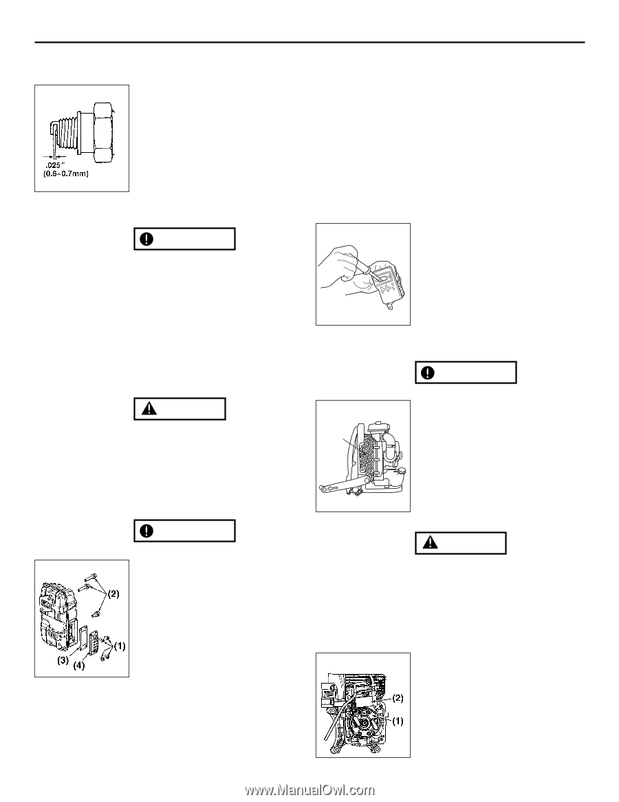
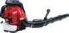
EBZ8500/RH 9. Maintenance ■ SPARK PLUG • The spark plug may gather carbon deposits on its firing end with F20 reasonable use. Remove and inspect the spark plug every 25 hours and clean the electrodes as necessary with a wire brush. The spark gap should be adjusted to .025 in (0.6~0.7mm). • Plug manufacturers recommend replacing the plug twice a year to avoid unexpected plug failure in a job. REPLACEMENT PLUG IS A NGK CMR7H. IMPORTANT F22 • Note that using any spark plugs other than those designated may result in the engine failing to operate properly or in the engine becoming overheated and damaged. • To install the spark plug, first turn the plug until it is finger tight, then tighten it a quarter turn more with a socket wrench. ■ MUFFLER WARNING • Inspect periodically, the muffler for loose fasteners, any damage or corrosion. If any sign of exhaust leakage is found, do not use the blower and have it repaired immediately. • Note that failing to do so may result in the engine catching on fire. F23 (1) IMPORTANT • Before starting operation, always make sure to check if the muffler is properly F21 held by three bolts (F21 (2)). (Fastening Torque : 8 to 12 N·m) • Also make sure that the speark arrester and the diffuser are properly attached with four bolts (F21 (1)). (Fastening Torque : 2 to 3 N·m) • Even if one of seven bolts is loose, it may result in engine catching on fire. F24 (1) Bolt (2) Bolt (4) Spark arrester (5) Diffuser US-14 ■ SPARK ARRESTER • The muffler is equipped with a spark arrester to prevent red hot carbon from flying out of the exhaust outlet. Periodically inspect and clean as necessary with a wire brush. In the State of California it is required by law (Section 4442 of the California Pulic Resources Code) to equip a spark arrester when a gas powered tool is used in any forest covered, bush covered, or grass covered unimproved land. ■ PROCEDURES TO BE PERFORMED AFTER EVERY 100 HOURS OF USE 1. Remove the muffler, insert a screwdriver into the vent, and wipe away any carbon buildup. Wipe away any carbon buildup on the muffler exhaust vent and cylinder exhaust port at the same time. 2. Tighten all screws, bolts, and fittings. ■ AIR INLET NET IMPORTANT • Blowing air is taken in from the air inlet net. When air flow has dropped down during operation, stop the engine and inspect the air inlet net not only out side but also bottom side for blocking by obstacles. • Note that failure to remove any such obstacles may result in the engine becoming overheated and damaged. (1) Net WARNING Never use the blower without the net of the blower. Before each use, check that the net is attached in place and is free from any damage. ■ IGNITION COIL AIR GAP INSPECTION • If the gap is out of standard or when installing the coil or rotor, adjust the air gap between the ignition coil and the iron core of the rotor. Air Gap: 0.30mm (0.3 ~ 0.4mm) 0.012" (0.012 ~ 0.016") (1) Rotor (2) Ignition coil
-
 1
1 -
2
-
3
-
4
-
5
-
6
-
7
-
8
-
9
-
10
-
 11
11 -
 12
12 -
 13
13 -
 14
14 -
 15
15 -
 16
16 -
 17
17 -
 18
18 -
 19
19 -
 20
20 -
 21
21 -
22
-
23
-
24
-
25
-
26
-
27
-
28
-
29
-
30
-
31
-
32
-
33
-
34
-
35
-
36
-
37
-
38
-
39
-
40
-
41
-
42
-
43
-
44
-
45
-
46
-
47
-
48
-
49
-
50
-
51
-
52
-
53
-
54
-
55
-
56
-
57
-
58
-
59
-
60
-
61
-
62
-
63
-
64
 |
 |