RedMax SGCZ2460S Owners Manual - Page 10
Set up
 |
View all RedMax SGCZ2460S manuals
Add to My Manuals
Save this manual to your list of manuals |
Page 10 highlights
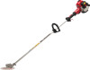
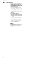
6. Set up SE1 SE2 SE3 ■ MOUNTING ENGINE (SE1) 1. Install the engine to the driveshaft so that the cylinder head and the stop switch may come on the same side. 2. Using attached four bolts, secure the connection firmly with equal force (Torque: 25in-lbs)(Torque: 2.8 N.m.). (1) Bolt (2) Stop switch SE4 WARNING Never use any screws other than those specified by the manufacturer, or the engine can get loose, resulting in a hazardous event. IMPORTANT Tighten the screws gradually by turns. ■ CONNECTING THROTTLE WIRE 1. Remove the air cleaner cover. 2. Connect the end of the throttle wire to the joint on the top of the carburetor. (SE2) ■ CONNECTING SWITCH WIRES • Connect the switch wires between the engine and the main unit. Pair the wires of the same color. SE5 ■ INSTALLING HANDLE • Mount the handle to the shaft tube and clamp it at a location that is comfortable to you. (SE3) (1) About 48cm SE6 SGCZ2460S ■ CUTTERCASE (SE4) WARNING The blade has very sharp edges. Be sure to use protective gloves U S whenever handling it. 1. Remove the fastening screw(long) and the lock screw(short) from the cuttercase. 2. While aligning the locking holes, install the cuttercase assembly to the shaft casing. 3. Align the locking holes and screw in the lock screw to the bottom by hand, then secure it with the wrench provided. Do not tighten up the lock screw with the holes out of alignment, or the cuttercase can be damaged. (1) Cuttercase (2) Locking holes NOTE If the locking screw is tightened up with the holes out of alignment, the cuttercase may be damaged. 4. Fasten the cuttercase fastening screw. ■ BLADE GUARD Install the blade guard onto the shaft casing approx. 3cm away from the cuttercase. Fasten the clamp uniformly. (SE5, SE6) US-9
-
 1
1 -
2
-
3
-
4
-
 5
5 -
 6
6 -
 7
7 -
 8
8 -
 9
9 -
 10
10 -
 11
11 -
 12
12 -
 13
13 -
 14
14 -
 15
15 -
16
-
17
-
18
-
19
-
20
 |
 |
