Reebok Rx9200 Treadmill English Manual - Page 7
Screws 10 into the Latch Insert and the Left Frame
 |
View all Reebok Rx9200 Treadmill manuals
Add to My Manuals
Save this manual to your list of manuals |
Page 7 highlights
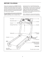
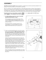
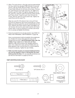
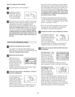
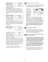
3. (Note: The parts shown in this step may be preassembled but may need to be adjusted.) With the help of a second person, raise the Frame (55) and hold it. Insert the Left Frame Guide (68) into the left side of the Frame. Remove the Latch Knob (67) from the Latch Pin (72). Make sure that the Latch Pin Collar (70) and the Spring (69) are on the Latch Pin. Insert the Latch Pin into the Frame and the Left Frame Guide. Press the Latch Insert (5) onto the Frame, with the Latch Pin in the center hole. Tighten the Latch Knob onto the Latch Pin. Align the Latch Pin (72) with the hole in the Left Foam Grip (62) by sliding the Left Frame Guide (68) up or down. Make sure that the Latch Pin can be inserted fully into the hole. Hold the Left Frame Guide in place and tighten two 1/2" Screws (10) into the Latch Insert and the Left Frame Guide. Note: It may be necessary to pull the Latch Knob (67) to access and tighten the Screws. 4. Raise the treadmill to the storage position (see HOW TO FOLD THE TREADMILL FOR STORAGE on page 24). Have a second person hold the treadmill in the upright position. Position the U-base (20) against the base of the Uprights (65) as shown, with the Bumpers (98) under the U-base. Finger tighten two 2" Bolts (26) with Base Washers (129) into the base of the Uprights and the Ubase. Then, attach the U-base with two 3" Bolts (23), two Base Washers (129), and two Nuts (13). Tip the treadmill forward if necessary. Tighten the two 2" Bolts. 5. Make sure that all parts are properly tightened before you use the treadmill. Place a mat beneath the treadmill to protect the floor. For your benefit, familiarize yourself with the information on pages 25 and 26. 3 Hole 68 62 55 10 5 70 72 69 67 4 13 26 129 23 13 26 65 129 98 20 98 23 PART IDENTIFICATION CHART Screw (40)-8 2" Bolt (26)-2 3" Bolt (23)-2 3/4" Screw (101)-4 Base Washer (129)-4 Nut (13)-2 Plastic Fastener (75)-4 7
-
 1
1 -
 2
2 -
 3
3 -
 4
4 -
 5
5 -
 6
6 -
 7
7 -
 8
8 -
 9
9 -
 10
10 -
 11
11 -
 12
12 -
13
-
14
-
15
-
16
-
17
-
18
-
19
-
20
-
21
-
22
-
23
-
24
-
25
-
26
-
27
-
28
-
29
-
30
-
31
-
32
-
33
-
34
 |
 |
