Ricoh Aficio SP C821DNLC Design Guide - Page 15
The standard IEEE1284 parallel I/F, USB I/F Type B, and Bluetooth I/F treat all incoming data
 |
View all Ricoh Aficio SP C821DNLC manuals
Add to My Manuals
Save this manual to your list of manuals |
Page 15 highlights
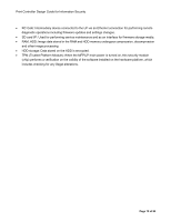
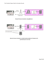
Print Controller Design Guide for Information Security 4. Communication between the MFP/LP and its peripherals is conducted via the peripheral I/F using Ricoh-unique protocols. These exchanges are limited to pre-determined commands and data, and only take place after the MFP/LP has recognized the peripheral device. If the MFP/LP receives illegal data from the peripheral, it will judge that a perhiperal device failure has occurred or that the device is not connected. This prevents any illegal access to internal programs or data. 5. The MFP communicates with external coin/card-operated devices through the External Charge Device I/F in accordance with the same protocols used for its peripherals described in #4 above. It is possible to utilize such devices in tandem with the access control settings for each user, in which case the device and MFP exchange the relevant information (e.g. User Code data). 6. With the @Remote function, the MFP/LP is connected via the network to a Ricoh-developed device known as RC Gate, which is then connected to the @Remote Center, or to the @Remote Center directly. When connecting to the center directly, the MFP/LP communicates via a LAN connection over the Internet. Before transferring any data, mutual authentication is performed using digital certificates between the MFP/LP and RC Gate or MFP/LP and @Remote Center, which ensures that the MFP/LP cannot connect to any device other than RC Gate or to its single, pre-assigned @Remote Center. Communication between RC Gate/@Remote Center and the MFP/LP modules responsible for @Remote operations is performed over exclusive socket-based connections, as described in #2 above. In addition, it is also possible to change the MFP/LP settings to prohibit @Remote communication. 7. External controllers are connected to the MFP via the Gigabit Ethernet-compatible network I/F, and are then routed internally through the external controller interface board. The internal arrangement is designed such that the external controller cannot gain access to the MFP internal modules until after it has successfully cleared the device registration process. In addition to sending data for printing to the MFP, the external controller is also capable of storing image data received from the PC inside its own memory as well as obtaining scanned data just following an MFP scanning job. It is not able to access any of the image data stored in the MFP. 8. The standard IEEE1284 parallel I/F, USB I/F (Type B), and Bluetooth I/F treat all incoming data as print data. This print data can only be sent to pre-specified modules responsible for executing printing operations. In addition, using MFP/LP settings, it is possible to disable each interface individually. 9. The USB I/F (Type A) only allows connection with devices that support either IC card-based authentication or PictBridge printing functions. Each function can be enabled/disabled individually. PictBridge printing functions (color MFP/LPs only): After the identity of the connected PictBridge device is verified, the interface and device exchange only pre-defined commands and/or data. Access to data stored inside the MFP/LP is not possible. In addition, if User Authentication has been enabled, the machine will not accept commands or data from any PictBridge functions that do not require authentication. Page 15 of 86
-
 1
1 -
2
-
3
-
4
-
5
-
6
-
7
-
8
-
9
-
 10
10 -
 11
11 -
 12
12 -
 13
13 -
 14
14 -
 15
15 -
 16
16 -
 17
17 -
 18
18 -
 19
19 -
 20
20 -
21
-
22
-
23
-
24
-
25
-
26
-
27
-
28
-
29
-
30
-
31
-
32
-
33
-
34
-
35
-
36
-
37
-
38
-
39
-
40
-
41
-
42
-
43
-
44
-
45
-
46
-
47
-
48
-
49
-
50
-
51
-
52
-
53
-
54
-
55
-
56
-
57
-
58
-
59
-
60
-
61
-
62
-
63
-
64
-
65
-
66
-
67
-
68
-
69
-
70
-
71
-
72
-
73
-
74
-
75
-
76
-
77
-
78
-
79
-
80
-
81
-
82
-
83
-
84
-
85
-
86
 |
 |