Rocketfish RF-TVMFM03 Quick Setup Guide (English) - Page 1
Rocketfish RF-TVMFM03 Manual
 |
UPC - 600603132223
View all Rocketfish RF-TVMFM03 manuals
Add to My Manuals
Save this manual to your list of manuals |
Page 1 highlights
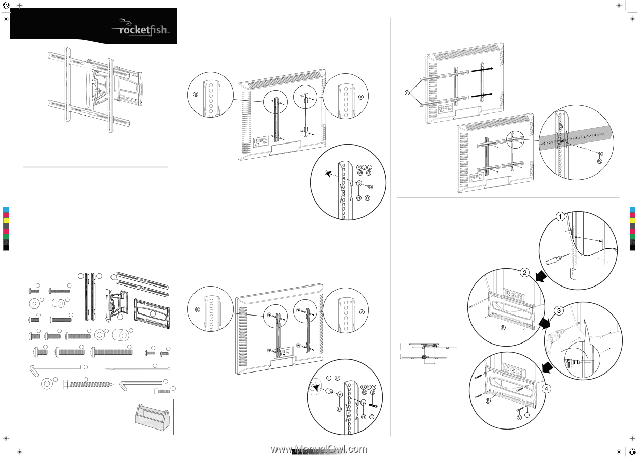
RF-TVMFM03_10-0726_QSG_V2_EN.eps 1 7/2/2010 1:18:59 PM QUICK SETUP GUIDE RF-TVMFM03 V2 FINAL FOR PRINT Note: Intended for use on wood stud walls with 16 in. or less spacing only. 1 Install the TV brackets Option 1: Installing for a flat mounting surface 1 Align the TV brackets (A and B) with the screw holes on the back of the TV. 2 Place the M4/M5 washers (H) or M6/M8 washers (O) over the holes in the TV brackets that align with the screw holes on the back of the TV, then insert the M4 screws (F), M5 screws (J), M6 screws (L or M), or M8 screws (Q) through the washers. 3 Tighten the screws until they are snug against the TV bracket. Do not over tighten. 2 Add the horizontal bars 1 Slide the horizontal bars (C) through the wire guides on the TV brackets. 2 Secure the bars to the TV brackets using the 9/16 in. × 8/32 in. Phillips head screws (W). Thank you for choosing the Rocketfish RF-TVMFM03. The RF-TVMFM03 TV mount is designed to support a flat-panel TV weighing up to 130 lbs. (58.9 kg). Package contents A Right vertical TV bracket (1) M8 bag B Left vertical TV bracket (1) Q M8 × 16 mm screws (4) C Horizontal TV bracket (2) R M8 × 40 mm screws (4) D Arm assembly (1) S M8 × 60 mm screws (4) E Wall plate (1) Hex key bag M4 bag C F M4 × 12 mm screws (4) M G M4 × 30 mm screws (4) Y H M4/M5 washers (8) CM I M4/M5 spacers (4) MY M5 bag CY J M5 × 12 mm screws (4) CMY K M5 × 30 mm screws (4) K M6 bag T 3/16 in. hex key (1) Lag bolt bag U Lag bolt washer (4) V 5/16 in. × 2-3/4 in. lag bolt (4) Bracket hardware W 9/16 in. × 8/32 in. Phillips head screw (4) X 3/8 in. × 8/32 in. Phillips head screw (1) Cable ties Y 8 in. nylon cable ties (5) L M6 × 12 mm screws (4) Cap screws M M6 × 20 mm screws (4) Z 5/32 in. hex key (1) N M6 × 35 mm screws (4) AA Cap screws (2) O M6/M8 washers (4) P M6/M8 spacers (4) A B C M4 bag F G M4 × 12 mm H M4 × 30 mm I M4/M5 M4/M5 M5 bag J K E D M5 × 12 mm M5 × 30 mm M6 bag L M N O P R or or 3 Install the wall plate to a wood stud wall Note: Any material covering the wall must not exceed 5/8 in. (16 mm). 1 Locate the studs. Verify the center of the stud with an awl Option 2: Installing for an obstructed mounting surface or thin nail or use an edge-to-edge stud finder. Note: Use additional washers (H) with M4/M5 hardware only. 1 Place the M4/M5 spacers (I) or M6/M8 spacers (P) and the M4/M5 washers (H) into the 2 Level the wall plate (E) and mark the hole locations.
-
 1
1 -
 2
2
 |
 |