Ryobi BGH6110 Trilingual (BGH6110) - Page 10
Assembly - accessories
 |
View all Ryobi BGH6110 manuals
Add to My Manuals
Save this manual to your list of manuals |
Page 10 highlights
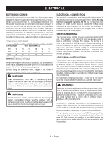
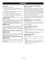
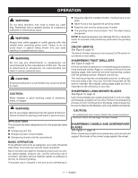
ASSEMBLY UNPACKING This product requires assembly. Carefully remove the tool and any accessories from the box. Make sure that all items listed in the Loose Parts are included. Inspect the tool carefully to make sure no breakage or damage occurred during shipping. Do not discard the packing material until you have carefully inspected and satisfactorily operated the tool. If any parts are damaged or missing, please call 1-800-525-2579 for assistance. WARNING: If any parts are damaged or missing do not operate this tool until the missing parts are replaced. Failure to do so could result in possible serious personal injury. WARNING: Do not attempt to modify this tool or create accessories not recommended for use with this tool. Any such alteration or modification is misuse and could result in a hazardous condition leading to possible serious personal injury. WARNING: Do not connect to power supply until assembly is complete. Failure to comply could result in accidental starting and possible serious personal injury. WARNING: Always spin the wheel by hand before turning on the grinder to make sure the spark deflector doesn't hit the grinding wheel. MOUNTING GRINDER TO WORKBENCH See Figure 5, page 14. The bench grinder must be mounted to a firm supporting surface such as a workbench or leg stand. Four bolt holes have been provided in the tool's base for this purpose. Each of the four mounting holes should be bolted securely using machine bolts, lock washers, and hex nuts (not included). Bolts should be of sufficient length to accommodate the saw base, lock washers, hex nuts, and the thickness of the workbench. Tighten all four bolts securely. Carefully check the workbench after mounting to make sure that no movement can occur during use. If any tipping, sliding, or walking is noted, secure the workbench to the floor before operating. MOUNTING SAFETY SHIELD ASSEMBLY See Figure 6, page 14. Attach the safety shield assembly and bracket to the wheel guard using a clamp bracket, washer, and hex head bolt. Tighten bolt securely. Repeat above steps for the other side. MOUNTING SPARK DEFLECTOR See Figure 6, page 14. Using the two phillips head screws, washers, and lock washers, attach the spark deflector to the top of the wheel guard. Adjust the spark deflectors to within 1/16 in. (1.6 mm) of the grinding wheel. Tighten screws securely. MOUNTING WORK REST See Figure 7, page 15. Unscrew and remove the carriage bolt from the work rest knob. Attach the work rest to the inside of the wheel guard as shown. NOTE: As the diameter of the wheel decreases with use, adjust the distance between the wheel and the work rest to maintain 1/16 in. or less separation. Tighten knob securely. 10 - English
-
 1
1 -
2
-
3
-
4
-
 5
5 -
 6
6 -
 7
7 -
 8
8 -
 9
9 -
 10
10 -
 11
11 -
 12
12 -
 13
13 -
 14
14 -
 15
15 -
16
-
17
-
18
-
19
-
20
-
21
-
22
-
23
-
24
-
25
-
26
-
27
-
28
-
29
-
30
-
31
-
32
-
33
-
34
-
35
-
36
-
37
-
38
-
39
-
40
 |
 |