Ryobi P20101BTL Parts Diagram - Page 3
Parts List
 |
View all Ryobi P20101BTL manuals
Add to My Manuals
Save this manual to your list of manuals |
Page 3 highlights
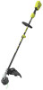
P20104/P20104VNM KEY NO. 1 2 3 4 5 6 7 8 9 10 11 12 PART NO. 315989001 940705585 661864007 660203052 313244003 292194001 315990001 760649001 539255001 314833001 315386001 308991003 DESCRIPTION Rear Handle Assembly (Inc. Key No. 2 & 13) Logo Label Screw (M4 x 18 mm, T15 Torx Pan Hd.) Screw (M3 x 8 mm, Pan Hd.) Motor & Gear Box Assembly Motor Controller & Switch Assembly Motor Volute Assembly Variable Speed Switch Hi-Lo Switch Cover Switch Trigger Assembly Boom Clamp Assembly Front Handle Assembly (Inc. Key Nos. 14-15) PARTS LIST QTY. KEY NO. PART NO. DESCRIPTION QTY. 1 941588484 Data Label (P20104) 1 13 1 941588902 Data Label (P20104VNM) 1 15 14 660643008 Screw (1/4-20 x 40 mm, Hex Hd.) 1 2 15 518949001 Wing Nut (1/4-20) 1 1 315991001 Boom Assembly (Inc. Key Nos. 18-20, P20104) 1 16 1 316009001 Boom Assembly (Inc. Key Nos. 18-20, P20104VNM) 1 1 17 690140011 Compression Spring 1 1 18 941013005 Warning Label (French/Spanish) 1 1 19 941851150 Attachment Capable Label 1 1 20 941588795 Warning Icons Label 1 1 Not Shown: 1 995000973 Operator's Manual 3
-
 1
1 -
 2
2 -
 3
3 -
 4
4
 |
 |
