Ryobi P2090 Parts Diagram - Page 3
Parts List
 |
View all Ryobi P2090 manuals
Add to My Manuals
Save this manual to your list of manuals |
Page 3 highlights
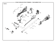
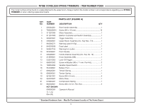
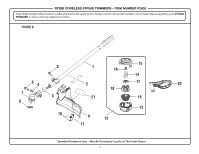
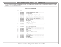
RYOBI CORDLESS STRING TRIMMERS - ITEM NUMBER P2009 The model number will be found on a label attached to the upper boom. Always mention the model number in all correspondence regarding your STRING TRIMMER or when ordering replacement parts. PARTS LIST (FIGURE A) KEY PART NO. NUMBER DESCRIPTION QTY 1 205004001 Rear Handle Assembly 1 2 T662028001 Screw (M4 x 16 mm 10 3 311291004 Motor Assembly 1 4 311291005 Electric Controller and Switch Assembly 1 5 205007001 Trigger Assembly 1 6 205003001 Upper Boom Assembly (Inc. Key Nos. 7-9 1 7 940006271 Warning Label (Fr/Sp 1 8 940028036 Data Label 1 9 940657185 Warning Icon Label 1 10 523409001 Front Handle 1 11 205006001 Handle Bracket Assembly (Inc. Key No. 12 1 12 313559001 Knob Assembly (M6 1 13 532076005 Lock-Off Trigger 1 14 660502002 Screw w/Washer (M5 x 11 mm, Pan Hd 2 15 760952002 Variable Speed Switch 1 16 534208001 Battery Foot 1 17 698420001 Torsion Spring 1 18 698399001 Torsion Spring 1 19 661861001 Screw (M4 x 8 mm 4 20 532076007 Motor Plate 1 21 679065001 Compression Spring 1 22 660203001 Screw (M3 x 8 mm, Pan Hd 2 NOT SHOWN 998000054 Operator's Manual 11-1-19 (Rev:09) * Standard Hardware Item - May Be Purchased Locally at The Home Depot 3
-
 1
1 -
 2
2 -
 3
3 -
 4
4 -
 5
5 -
 6
6
 |
 |
