Ryobi P360 User Manual 2 - Page 3

Parts List - stapler

Page 3 highlights

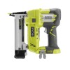
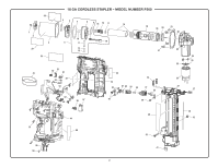
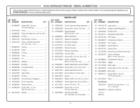
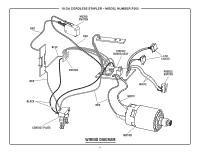
18 GA CORDLESS STAPLER - MODEL NUMBER P360 The model number will be found on a label attached to the motor housing. Always mention the model number in all correspondence regarding your RYOBI STAPLER or when ordering repair parts. KEY PART NO. NUMBER DESCRIPTION QTY 1 661858001 Screw (M3 x 16 mm, T10 Torx Flat Hd 1 2 524473001 Knob 1 3 202642001 Piston Cylinder (Inc. Key No. 29)...1 4 562962001 O-Ring 1 5 305672001 Valve Holder w/Insert 1 6 206151001 Piston and Rod Assembly (Inc. Key Nos. 7-14 1 7 562959001 O-Ring 1 8 524451001 Piston 1 9 562958001 O-Ring 1 10 202641001 Filter 1 11 673090001 Pin 1 12 693291001 Magnet 1 13 524752001 Bumper 1 14 693099003 Connecting Rod 1 15 562961001 O-Ring 1 16 524475001 Valve Shaft 1 17 562960001 O-Ring 1 18 305684001 Drive Cylinder w/Magnet 1 19 202918001 Driver Assembly 1 20 562963001 Rubber Sleeve 1 21 661923001 Screw (M4 x 14 mm, T20 Torx Pan Hd 4 22 634212001 Gasket 1 PARTS LIST KEY PART NO. NUMBER DESCRIPTION QTY 23 202920001 Crank Case and Gear Assembly...1 24 660212005 Screw (M4 x 8 mm, Pan Hd.)........2 25 670030004 Spring Washer (OD7.2 x ID4.1 x 1t 2 26 202606001 Motor Assembly 1 27 202921001 Magazine Assembly 1 28 918003016 Warning Hangtag 1 29 941007015 Air Strike Label 2 30 562964001 Rubber Bumper 1 31 941120019 Warning Hang Tag 1 32 670974003 Hex Nut (M5 1 33 660180005 Screw (M5 x 32 mm, Soc. Hd.).....1 34 661749001 Screw w/Washer (M4 x 19 mm, Soc. Hd 2 35 635029001 Depth Adjustment Crank Handle..1 36 T661853001 Screw (M4 x 4 mm, Soc. Hd.).......1 37 305671001 Depth Adjustment Knob 1 38 661743001 Screw (M2.5 x 18 mm, Hex)..........1 39 693475001 Spring 1 40 690046001 Washer (OD14.8 x ID10.5 x 0.5t)...1 41 524688001 Depth Adjustment Knob Holder....1 42 661742001 Screw (T10 Torx, T.F 1 43 660380008 Screw (M3 x 10 mm, T10 Torx Pan Hd 2 44 202919001 Housing Assembly (Inc. Key Nos. 45, 49 and 58)........1 KEY PART NO. NUMBER DESCRIPTION QTY 45 940114178 Logo Label 1 46 941007012 Danger Label (Magazine 1 47 525814001 No-Mar Pad 2 48 941001071 Worklight Label (LED 1 49 941001094 POP Label 1 50 692784001 Compression Spring 1 51 524852001 LED Trigger 1 52 524689001 Mode Selector 1 53 634401001 Spring Plate 1 54 270013096 Switch/Circuit Board Assembly.....1 55 661902001 Screw w/Washer (M2 x 14 mm, Pan Hd 2 56 693688001 Compression Spring 1 57 524418001 Trigger 1 58 941121240 Data Label 1 59 660212001 Screw (M4 x 6 mm, Pan Hd.)........1 60 633586002 Belt Hook 1 61 660031011 Screw (M3.5 x 16 mm, T10 Torx Pan Hd 9 62 635100001 Plate 1 Not Shown: 202922001 Seal Kit (Inc. Key Nos. 4, 7, 9, 15, 17 and 20) 990000748 Operator's Manual 1-27-14 (Rev:01) 3

  • 1
  • 2
  • 3
  • 4

18 GA CORDLESS STAPLER – MODEL NUMBER P360
3
The model number will be found on a label attached to the motor housing. Always mention the model number in all correspondence regarding your
RYOBI STAPLER
or when ordering repair parts.
PARTS LIST
1 661858001
Screw (M3 x 16 mm,
T10 Torx Flat Hd.)
.........................
1
2 524473001 Knob
.............................................
1
3 202642001
Piston Cylinder (Inc. Key No. 29)..1
4 562962001 O-Ring
..........................................
1
5 305672001 Valve Holder w/Insert
...................
1
6 206151001 Piston and Rod Assembly
(Inc. Key Nos. 7-14)
......................
1
7 562959001 O-Ring
..........................................
1
8 524451001 Piston
...........................................
1
9 562958001 O-Ring
..........................................
1
10 202641001 Filter
..............................................
1
11 673090001 Pin
................................................
1
12 693291001 Magnet
.........................................
1
13 524752001 Bumper
.........................................
1
14 693099003 Connecting Rod
...........................
1
15 562961001 O-Ring
..........................................
1
16 524475001 Valve Shaft
....................................
1
17 562960001 O-Ring
..........................................
1
18 305684001 Drive Cylinder w/Magnet
..............
1
19 202918001 Driver Assembly
...........................
1
20 562963001 Rubber Sleeve
..............................
1
21 661923001
Screw (M4 x 14 mm,
T20 Torx Pan Hd.)
.........................
4
22 634212001 Gasket
..........................................
1
KEY PART
NO. NUMBER
DESCRIPTION
QTY
KEY PART
NO. NUMBER
DESCRIPTION
QTY
KEY PART
NO. NUMBER
DESCRIPTION
QTY
23 202920001
Crank Case and Gear Assembly ..1
24 660212005
Screw (M4 x 8 mm, Pan Hd.)
.......
2
25 670030004 Spring Washer
(OD7.2 x ID4.1 x 1t)
......................
2
26 202606001 Motor Assembly
...........................
1
27 202921001 Magazine Assembly
.....................
1
28 918003016 Warning Hangtag
..........................
1
29 941007015 Air Strike Label
.............................
2
30 562964001 Rubber Bumper
............................
1
31 941120019 Warning Hang Tag
........................
1
32 670974003 Hex Nut (M5)
................................
1
33 660180005
Screw (M5 x 32 mm, Soc. Hd.)
....
1
34 661749001 Screw w/Washer
(M4 x 19 mm, Soc. Hd.)
...............
2
35 635029001
Depth Adjustment Crank Handle .1
36
T661853001 Screw (M4 x 4 mm, Soc. Hd.)
......
1
37 305671001 Depth Adjustment Knob
...............
1
38 661743001
Screw (M2.5 x 18 mm, Hex)
.........
1
39 693475001 Spring
...........................................
1
40
690046001
Washer (OD14.8 x ID10.5 x 0.5t) ..1
41 524688001
Depth Adjustment Knob Holder ...1
42 661742001 Screw (T10 Torx, T.F)
....................
1
43 660380008
Screw (M3 x 10 mm,
T10 Torx Pan Hd.)
.........................
2
44 202919001 Housing Assembly
(Inc. Key Nos. 45, 49 and 58)
.......
1
45 940114178 Logo Label
....................................
1
46 941007012 Danger Label (Magazine)
..............
1
47 525814001 No-Mar Pad
..................................
2
48 941001071 Worklight Label (LED)
...................
1
49 941001094 POP Label
....................................
1
50 692784001 Compression Spring
.....................
1
51 524852001 LED Trigger
...................................
1
52 524689001 Mode Selector
..............................
1
53 634401001 Spring Plate
..................................
1
54 270013096 Switch/Circuit Board Assembly
....
1
55 661902001 Screw w/Washer
(M2 x 14 mm, Pan Hd.)
.................
2
56 693688001 Compression Spring
.....................
1
57 524418001 Trigger
...........................................
1
58 941121240 Data Label
....................................
1
59 660212001
Screw (M4 x 6 mm, Pan Hd.)
.......
1
60 633586002 Belt Hook
......................................
1
61 660031011
Screw (M3.5 x 16 mm,
T10 Torx Pan Hd.)
.........................
9
62 635100001 Plate
.............................................
1
Not Shown:
202922001
Seal Kit (Inc. Key Nos. 4, 7, 9,
15, 17 and 20)
990000748 Operator's Manual
1-27-14
(Rev:01)