Ryobi P591 Parts Diagram - Page 3

Parts List - - shears

Page 3 highlights

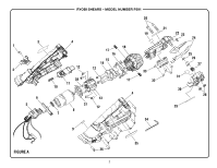
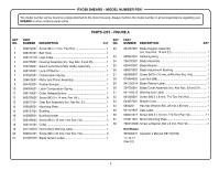
RYOBI SHEARS - MODEL NUMBER P591 The model number will be found on a label attached to the motor housing. Always mention the model number in all correspondence regarding your SHEARS or when ordering repair parts. PARTS LIST - FIGURE A KEY PART KEY PART NO. NUMBER DESCRIPTION QTY NO. NUMBER DESCRIPTION QTY 1 660212057 Screw (M4 x 7 mm, Pan Hd 1 22 204757001 Blade Support Assembly 2 636181001 Belt Hook 1 (Inc. Key Nos. 19 and 21 1 3 940114178 Logo Label 1 23 690924001 Retaining Ring 1 4 204755001 Housing Assembly (Inc. Key Nos. 3 and 35 1 24 206702001 Blade Assembly 1 5 204756001 Switch w/Contact Plate Holder Assembly 1 25 639404001 Blade Washer 1 6 360135001 Lock-Off Button 1 26 696075002 Blade Adjustment Bushing 1 7 672552001 Compression Spring 1 27 662688001 Screw (M10 x 10 mm, w/M5 Hex Soc. Hd 1 8 206670001 Motor and Pinion Assembly 1 28 670494002 Lock Nut (M6 2 9 564433001 Rubber Bumper 1 29 941120314 Blade Tension Label 1 10 694934001 Latch Compression Spring 1 30 204758001 Blade Cover Assembly (Inc. Key Nos. 29 and 31)......... 1 11 360140001 Collar Release Button 1 31 941120315 Warning Icon Label 1 12 660250002 Screw (M3.5 x 14 mm, Pan Hd 8 32 661268001 Screw (M3.5 x 8 mm, T15 Torx Pan Hd 4 13 206671001 Gear Box Assembly (Inc. Key No. 37 1 33 643067001 Middle Cover 1 14 639045001 Mounting Plate 1 34 6800201 Hex Key Wrench (M5, 28 mm x 80 mm 1 15 639727001 Bushing 1 35 941121837 Data Label 1 16 643068001 Bushing Holder 1 36 660031017 Screw (M3.5 x 16 mm, T10 Torx Pan Hd 11 17 660169044 Screw (M4 x 10 mm, Hex Soc. Hd 2 37 513611001 Motor Mounting Plate 1 18 360141001 Collar 1 38 T662103001 Screw w/Washer (M4 x 6 mm, Pan Hd 2 19 941120316 Hot Surface Warning Label 1 Not Shown 20 662627001 Screw (M6 x 35 mm, Hex Soc. Hd 2 995000241 Operator's Manual (961152709) 21 941007075 Blade Tension Label 1 11-16-17 (Rev:01) 3

  • 1
  • 2
  • 3
  • 4

3
RYOBI SHEARS – MODEL NUMBER P591
The model number will be found on a label attached to the motor housing. Always mention the model number in all correspondence regarding your
SHEARS
or when ordering repair parts.
PARTS LIST – FIGURE A
KEY
PART
NO.
NUMBER
DESCRIPTION
QTY
KEY
PART
NO.
NUMBER
DESCRIPTION
QTY
1
660212057
Screw (M4 x 7 mm, Pan Hd.)
........................................
1
2
636181001 Belt Hook
......................................................................
1
3
940114178 Logo Label
....................................................................
1
4
204755001
Housing Assembly (Inc. Key Nos. 3 and 35)
.................
1
5
204756001 Switch w/Contact Plate Holder Assembly
....................
1
6
360135001 Lock-Off Button
............................................................
1
7
672552001 Compression Spring
.....................................................
1
8
206670001 Motor and Pinion Assembly
..........................................
1
9
564433001 Rubber Bumper
.............................................................
1
10
694934001 Latch Compression Spring
...........................................
1
11
360140001 Collar Release Button
...................................................
1
12
660250002
Screw (M3.5 x 14 mm, Pan Hd.)
...................................
8
13
206671001
Gear Box Assembly (Inc. Key No. 37)
...........................
1
14
639045001 Mounting Plate
..............................................................
1
15
639727001 Bushing
.........................................................................
1
16
643068001 Bushing Holder
.............................................................
1
17
660169044
Screw (M4 x 10 mm, Hex Soc. Hd.)
..............................
2
18
360141001 Collar
.............................................................................
1
19
941120316 Hot Surface Warning Label
...........................................
1
20
662627001
Screw (M6 x 35 mm, Hex Soc. Hd.)
..............................
2
21
941007075 Blade Tension Label
......................................................
1
22
204757001 Blade Support Assembly
(Inc. Key Nos. 19 and 21)
..............................................
1
23
690924001 Retaining Ring
...............................................................
1
24
206702001 Blade Assembly
............................................................
1
25
639404001 Blade Washer
................................................................
1
26
696075002 Blade Adjustment Bushing
...........................................
1
27
662688001
Screw (M10 x 10 mm, w/M5 Hex Soc. Hd.)
..................
1
28
670494002 Lock Nut (M6)
................................................................
2
29
941120314 Blade Tension Label
......................................................
1
30
204758001
Blade Cover Assembly (Inc. Key Nos. 29 and 31)
........
1
31
941120315 Warning Icon Label
.......................................................
1
32
661268001
Screw (M3.5 x 8 mm, T15 Torx Pan Hd.)
......................
4
33
643067001 Middle Cover
.................................................................
1
34
6800201
Hex Key Wrench (M5, 28 mm x 80 mm)
.......................
1
35
941121837 Data Label
.....................................................................
1
36
660031017
Screw (M3.5 x 16 mm, T10 Torx Pan Hd.)
..................
11
37
513611001 Motor Mounting Plate
...................................................
1
38
T662103001 Screw w/Washer (M4 x 6 mm, Pan Hd.)
.......................
2
Not Shown
995000241 Operator's Manual (961152709)
11-16-17
(Rev:01)